N6GN Remote KiwiSDR
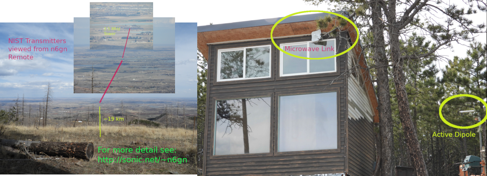
This KiwiSDR is located on a mountain top/side about 7500’ ASL and 2500’ above the plain directly to its east. It is located on a significant slope which gives it a low take-off-angle for reception in that direction. While the hardware tends to change, generally it is an antenna of some sort along with a KiwiSDR which is accessed via a 5 GHz microwave link to N6GN home QTH located on the south side of Fort Collins, Colorado. The time base for the KiwiSDR is a Bodnar GPSDO and accuracy and stability are generally as good as one part-per-billion. The Kiwi’s IQ extension can be used to compare that time base with line-of-sight transmissions from NIST, the National Institute of Standards and Technology. Because this US primary frequency standard signal is not ionospherically propagated, its accuracy actually becomes available to an HF receiver so that the Bodnar’s characteristics can be directly measured.
The remote site is approximately SW of the NIST transmitters, WWVB at 60 kHz and the six WWV HF transmitters near Wellington, Colorado at 2.5,5,10,15,20 and 25 MHz. See the NIST/WWV page for details.
Due to the slope, a low take-off-angle toward the East for the receive antennas is produced. Also, the nearest power mains is about .6 miles distant so the site is pretty quiet, except for self-induced QRN such as from the solar charge controller (daytime f<120 kHz) and switched-mode-power supply (f~960 kHz) that provides 5 VDC for the KiwiSDR, external clock and microwave link. The solar panel power source is backed up with a 12V storage cell which keeps everything operational at nighttime.
Signal strength from the NIST transmitters is quite large. At only 20 km distance, the 70 kW ERP (according to Wikipedia) WWVB can be a challenge.
Expected signal level in a short dipole terminated into the high impedance OpAmp of the present active antenna is not constant with frequency due to very-low-frequency mismatch loss. The following plot shows this loss along with the expected signal level from a unity gain preamplifier. The ITU-R P.372-8 noise model data for ‘noisy’ and ‘quiet’ sites are given as are contributors and total expected receiver noise for the active antenna presently in use.

70 kW ERP at 19 km can be estimated to produce a power density in free space of about
![]()
This should correspond to an electric field strength of
![]() Calculators that include ground effects arrive at levels of about 120
mV per meter.
Calculators that include ground effects arrive at levels of about 120
mV per meter.
Measured signal from the lightly loaded 1.9m dipole antenna transferred to a 50 ohm load is about -4 dBm or 141 mV indicating a field strength of 74 mV/meter. This seems to agree and be within measurement uncertainty but I’m still investigating these indicated ERP, estimates and calculations. Something is not adding up yet.
Since it is desired to hear weak signals, that is, to hear the propagated noise floor at any desired frequency within the KiwiSDR’s 10 kHz-30 MHz range, not only must overload be managed but also receive system sensitivity.
To provide for this 10 kHz-30 MHz spectrum an active antenna is in use. This antenna comprises a ~2 meter tip-tip dipole along with low noise, very high impedance unity gain OpAmp followers on each monopole of that dipole. These two outputs are inputs for a CAT5 line driver IC. The CAT5 cable is received at the KiwiSDR location by a line receiver on a second PCB near the KiwiSDR. This arrangement maintains high common mode rejection ratio and finally converts the differential antenna signal to single-ended where it is subsequently filtered and/or attenuated as necessary prior to the KiwiSDR input connector.
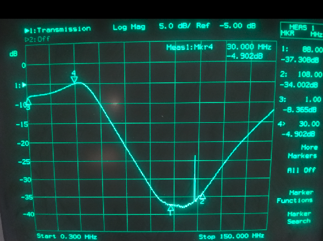
Another problem on the hilltop is that of very strong FM broadcast signals. At the 2m dipole signal voltages exceed .5 Volt peak-peak. Since the input of the OpAmp is very high impedance, there is no easy way to filter these signals and protect the active stages from generating IMD. At the output of the first preamp, however, there is some filtering which helps protect downstream stages. Here is the swept response of a unity-gain preamplifier driving 60 feet of CAT5 cable which is received by a second differential amplifier at the Kiwi:
Since the KiwiSDR’s ADC has a maximum signal limit of about -14 dBm (50 ohms reference at the KiwiSDR SMA input) it is necessary to be sure that the instantaneous vector sum of all incoming signals whether from NIST or other transmitters, stay below this level. At the same time, the noise associated with the equivalent antenna temperature for a quiet site, as described by the ITU, should be transferred to the KiwiSDR and dominant. This combination of strong signal handling and low noise, high-sensitivity operation is a challenge for the best of amplifiers. Simultaneously achieving these goals strong signal and low noise, including low noise and intermodulation distortion (IMD) at a remote site is an ongoing challenge.
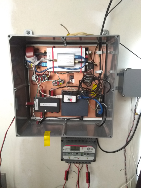
A combination 60 kHz trap and MW band stop filter is used to limit the incoming signal at the KiwiSDR input. Hardware inside the ‘shack’ looks like this:
In addition to the high dynamic range requirements of this remote receiver site, weather is a factor. Northern Colorado commonly has intense thunder and lightning storms, particularly in the Springtime. A broad spectrum antenna solution for this remote site also needs to have some robustness against nearby lightning strikes. Storms that produce local mountainside strikes at a rate greater than one-per-minute are not uncommon.
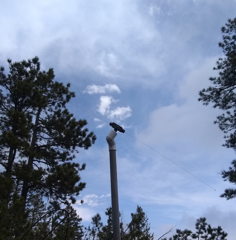
Here is a picture of the .01-50 MHz N6GN 2m active antenna in use as of May 2019 It consists of two monopoles with very high impedance OpAmp followers and CAT5 line driver. At the Kiwi location there is a companion differential CAT5 receiver followed by filtering and the Kiwi itself.
This document describes an initial andongoing attempt to solve the above problem. If everything is operating normally, you may be able to observe the results at http://n6gn.no-ip.org:8075
Glenn n6gn
April 2019