Johnny's Rocket Gallery

Photos and such of my rediscovered hobby: Back to the Rockets Page

Note: most or all of the links below will open in a new browser window.


Apogee Saturn 1B

What a great kit. I'd never been interested in scale model rockets, but the Saturn 1B was such a beautiful rocket and the Apogee kit just seemed so well done.

I based the detail of my model on the Apollo 7 rocket, which was also arguably one of the most beautiful launches of all time.

Tim Van Milligan, et al. did an excellent job on this. You can start to see the level of the detail from this picture (click for detail).

I hope to have some additional information about the construction, with some personal hints on construction and such. You can find out more in the mean time at the Apogee Saturn 1B web site.

I have yet to launch it - but I plan to soon!


Lectro Launch

Way back when™, I dreamed of building my own launch controller. I'd seen the parts in the old Centuri catalog and knew it would have jeweled lights and a key switch. Well, I decided to see what I could do. I decided this would be a retro project, using all electromechanical parts. No solid state switches, logic chips, no LEDs. This would be mechanical switches, light bulbs and relays.

I also had a few other issues impacting the design.

  • I'd had a couple of launches using a AA launcher where after several launches, it would take several seconds to fire the igniter.
  • On one occasion, even though I had the young man doing a launch put the strap on the safety key around his neck, in the excitement of the launch, rather than pull out the "key" (piece of wire), he went to the trouble to pull the loop over his head, dropping the controller to the ground, still armed. I wanted something teenager proof (or as near as I could get)
  • I wanted a wire to the pad that you could actually see
  • I needed something that would fire the larger igniters my new Hi-Tech H45 would need.

I picked up a pair of four pole, double throw relays, figuring that would have to be enough. It wasn't. I used nearly every contact on the relays and still wound up with a substandard design. For instance, at one point in the design, the green safety light would have been on while full current was being delivered to the igniter. Difficult to trust such a "SAFE" light.

The current design only lets the green safety light come on when the igniter contacts are grounded together. I'm pretty happy with the overall design and am looking forward to giving it a good shake down soon. Among the features are:

  • Loss of power disarms the controller
  • A press and release of the fire button when armed, even for just a moment disarms the controller to SAFE.
  • Continuity is active when key switch is in STANDBY or ARM conditions
  • Key must be returned to at least STANDBY to rearm after a launch
  • A short circuit will cause the launcher to disarm and drop to Safe/Green in a fraction of a second
The last feature I stumbled upon. I went directly from a schematic to a fully wired set of relays. (My plans to test it in phases fell apart as once I got a-soldering, I kept on going!). It worked beautifully first time, every time, until I tried shorting the contacts. It's fused (man is it fused - there are five fuses [not all "intentional"] between the battery and the igniter). I first just tried a very short push of the launch button and noticed it didn't disarm. I tried longer and longer pushes of the launch button until finally one of the fuses blew. I traced the problem down to the fact that shorted, the voltage dropped to a point still high enough to hold the arming and firing relays, but not enough to close the disarming relay - the mechanism that forces the reset to Safe/Green.

With some carefully selected resistors, I was able to create a design where the lowered voltage of a full short would cause the arming and launch relays to drop out, but with every igniter I tried, including an Aerotech Copperhead igniter, there was no problem setting it off and the relays held just fine. (Just in case, the short circuit protection can be disabled by opening the controller and flipping an internal switch.)

I had an image in my mind, but wasn't sure it would turn out - I felt I'd know it when I saw it. This wasn't quite what I imagined, but it came pretty close:


Click for larger version in a separate window

Shown here from the center and working clockwise are:

  • The "LectroLaunch" controller with integrated power cables, voltmeter, key switch and cool looking lights!
  • 12V 4.3amp-hour gel cell case. The small button below the power jack and between the light and fuse activates the light and voltmeter. The light is to put a small load on the battery, give a quick, qualitative view of the battery strength and also helps for reading the meter in the dark (I also use an identical setup for remote recording).
  • 50' 12ga neon orange extension cord. I got tired of people tripping over that tiny, dark brown cable with the Estes launcher. The power plug at the far end also includes a flashing LED that just happens to light visibly with only continuity current (but only if the igniter is not connected)
  • Microclip igniter attachment
  • Aerotech clip for Copperhead, Tigertail and similar igniters
  • "test" plug with flashing LED in the end.
  • The all-important key. One nice feature is that the launcher can be armed and the key removed. Once the launch button is pressed and released, there is no way to rearm the controller without the key.

The operation is pretty straight forward. When connected to the battery, the green light comes on - unless the key switch was left in STANDBY. (If the switch is in the ARM position, the controller comes up "SAFE"). The voltmeter displays the battery voltage and when the key is put into the SAFE position, the green "Safe" light comes on. The extension is plugged into the controller and run to the pad. The appropriate igniter clip is plugged in and hooked to the igniter. Note that if the controller is not "SAFE" the end of the extension will flash. The LED is visible even in direct sunlight, though you'd need to be close and looking at it. The presumption is that those would both be true when you're plugging in the igniter clip.

Once hooked up, the key is switched to STANDBY. The arming relay powers up, the Safe light goes out, and if there is continuity, the yellow light by the same name comes on. When all's well, the key switch is switched to ARM. This connects the launch switch and the red "Armed" light to power via the arming relay.

When the launch switch is pushed, several things happen. The launch relay trips, connecting the igniter directly to the battery through two sets of contacts. In addition, another set of contacts is used to continue to supply power to the launch switch. This is necessary because the fourth and final set of contacts energizes the disarming relay. Its only purpose is to open the arming relay. The upshot of this is that when you press and hold the launch button, all three relays click in very rapid succession (I generally cannot hear the individual relays) and power is connected to the igniter. Once the launch button is released, the launch relay drops and the launch controller reverts to the Safe/Green condition.

Switching to STANDBY and back to ARM rearms the controller, though normal operation is to switch to SAFE until the next launch is ready.

This could have been done with logic circuits and power transistors and I may yet do something like that, but the point here was to come up with something fun, but also something that would quickly, reliably and safely fire igniters of various sizes. After a couple of five second delays with those AA powered controllers, I'm looking forward to the instant results I get with this. I've tested this with dozens of igniters of different types and had excellent results. It also always disarms on launch if there is a short circuit.

I may eventually post the plans here - but not before I've done more testing This is a safe design, but it's also complicated to build. Built incorrectly it could be dangerous. We'll see how it goes.


The ReAvenger Saga

This deals with an unconventional and largely untested method of multistaging. PLEASE don't consider this method safe or tested.

Back in the day, around 1972 or so, I bought the biggest rocket I'd owned so far - the Estes Avenger. It was a two stage rocket and used the classic Estes staging and mounting method of using cellophane tape to hold the motors together for staging and masking tape for the friction fit to hold the motors in place.

I launched it once and it flew well. However, on recovery I discovered that even though the second stage had lit fine, at separation the first stage engine broke loose of the first stage leaving the first stage still attached. The second stage burned normally, but its exhaust went through the first stage where the motor had just been. This burned out the engine mount. The top part was fine, but at the bottom of the first stage, the engine mount was completely burned away. Luckily, the rocket body was in good shape.

This is the way it sat for years in my parent's attic. During a clean up they sent the rockets back my way and the Avenger lived in my closet for several more years. When a launch opportunity approached, I decided to see if I could resurrect some of the old rockets, including my original Alpha and the Avenger.

Because of the way the engine had blown out, I was resolved to find a way to hold the motors better than using masking tape. I also decided since I was replacing the motor mount, I might as well upgrade to a D engine mount. I did some fitting and tests and came up with something that looked like it would work. To compensate for the additional weight in the rear, I added nose weight in the way of metal washers attached to the nose cone eyelet.

I first flew it single stage and it flew well, but a fin broke off on recovery so that was it for that day. About a year later I decided to try a two stage launch, but with something smaller than a D. In the mean time, I'd gotten a copy of the G. Harry Stine Handbock of Model Rocketry. I'd learned from the chapter on multistaging about the importance of holding the stages together for a few milliseconds so that the hot gas and particles of burning fuel could enter the upper stage motor before the shockwave blew them apart.

The problem here was that I had motor mount clips on both the upper and lower stage mounts - there was no way to get the tape around the motors and still assemble the rocket. What to do? I settled on hot glue. I put a good sized ring of hot glue on the top of the first stage motor, the adapter (since I was using an 18mm motor in a 24mm mount) and the mount. I was careful to keep the glue away from the propellent in the first stage. I then assembled the stages quickly and let the glue set.

Since this was a test, I used as small an engine as I dared (not sure which one, but most likely a B6-0 - I miss those old B14-0 boosters!). and a small A engine for the upper stage. If it didn't stage, I didn't want it getting very high.

It staged beautifully, though it appeared the stages held together for a second or so, the upper stage thrust simply venting through the lower stage nozzle until the hot glue melted and it released.


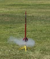
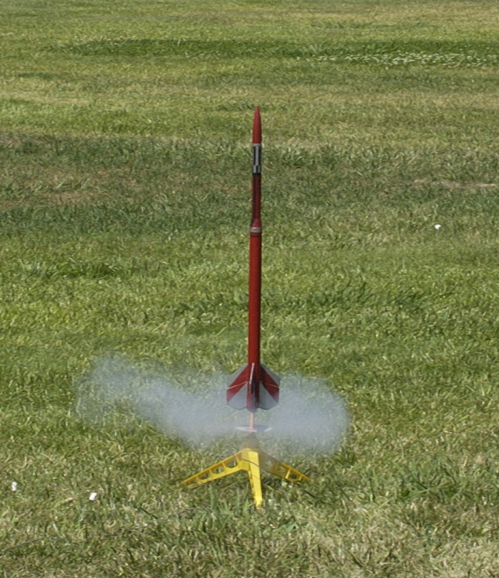
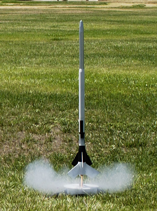
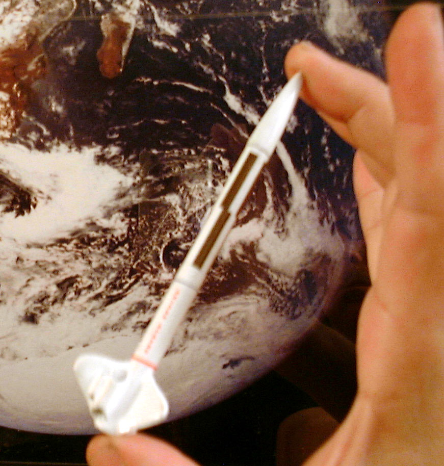
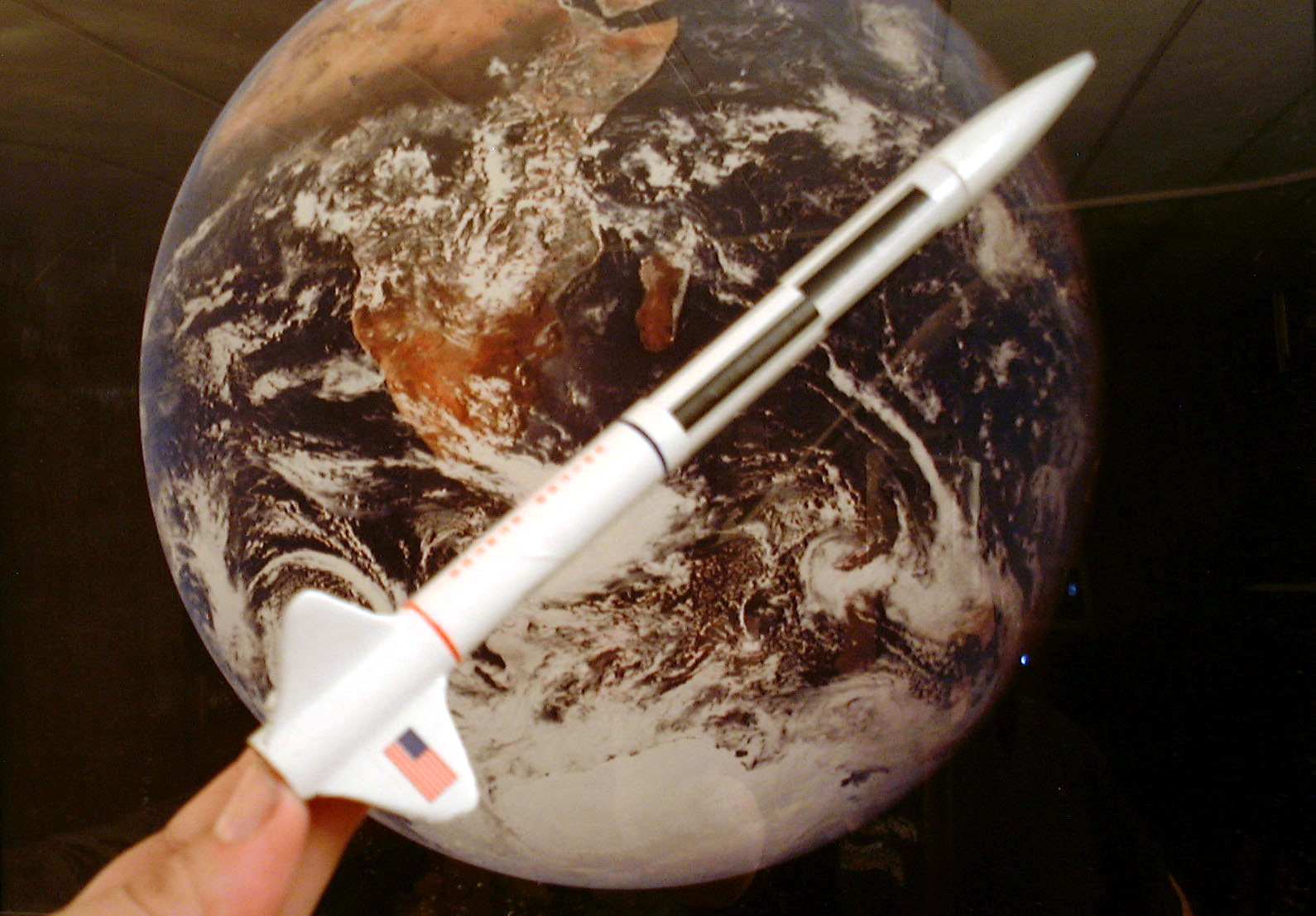
Avenger launch, June 2002 - click for larger image

About a year later at our next launch, June of 2002, I was ready to try the old Avenger with an Estes D12-0 first stage. This time I used a bit less hot glue to prevent the delay in separation.

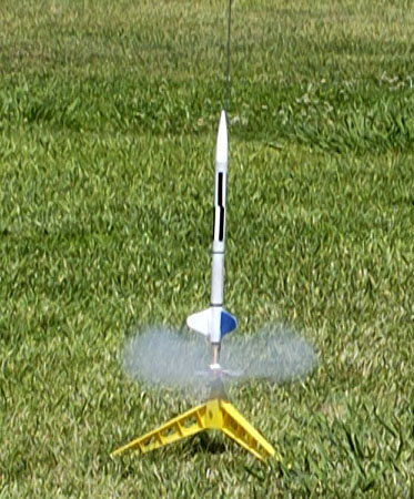
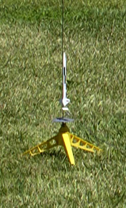
This turned out to be essentially fatal for the rocket. The first stage portion of the flight went well, but it was obvious right away that the stages separated before the upper stage lit. The first stage tumbled down and was soon passed by the upper stage coming straight down. It hit on reasonably hard ground and pretty much disintegrated.


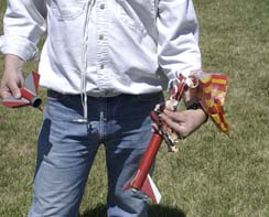
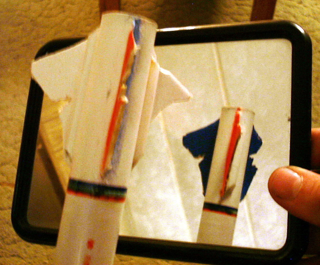
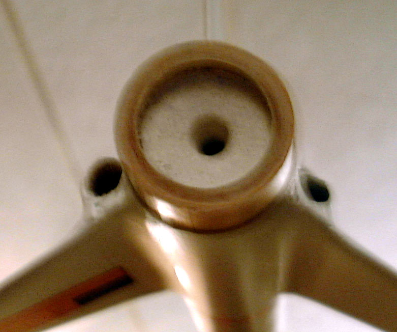
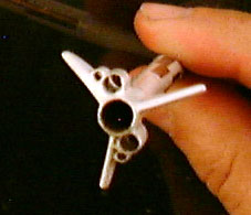
Avenger Aftermath - click for larger image

I decided to see what I could do with the parts that survived. The nose cone was in surprisingly good shape. The balsa transistion, one of the fins from the upper stage and the entire lower stage survived (actually, you can probably see in the photo that two fins survived the landing, but only one of them survived being removed). Oh, and don't forget the launch lug.

My construction back when I was 14 or so, was, well, somewhat impatient. Two not quite matching shades of red had been used, one of which was house paint, the balsa was not noticably filled and I'd actually used electrical tape for some details.

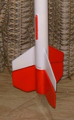
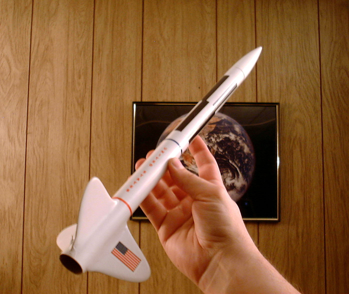
I took the surviving pieces, sanded and filled the balsa and replaced the destroyed pieces - the two pieces of tubing, the upper stage motor mount (also didn't survive the deconstruction) and two of the upper stage fins. It came together nicely and I settled on a fun paint scheme: all new parts were white, the parts still surviving from the original were red.


The new, clean look:
White is new, Red is original

Dig the surviving launch lug

I have yet to fly it, but if I do, I'll use more rather than less hot glue, that's for sure.

NOTE: While hot glue is not hot enough to set off the propellent, using an electrically heated device near a flammable substance should at least be done carefully. Keep the metal tip away from the propellent. Keep glue out of the space between the stages as it could prevent staging.

I cannot recommend this method as I have not had enough launches to know if it's safe and reliable. Don't try this unless you're confident that you can deal safely with the consequences of a failed upper stage ignition as well as the hot glue process.


The Skylifter Project

More here later. This is an experimental multistage design with a wadding-less ejection system. It is intended as a lifter for a micro video camera and transmitter.


SkyLifter, 2 stage configuration
click for larger image


The Arcon Series

Once I laid eyes on the newer Estes E motors, I decided to try a minimum diameter rocket built around that motor. with reasonably good performance. The Stine book suggested a long, thin core, with elliptical fins might do well. I designed this prototype with 1/16" balsa fins and a quick, patriotic paint job and decided to try it.


Original Arcon, B engine
click for larger image

In the larger version of the image above, you can notice a few features of the design:

  • Fin shape based loosely on the wing shape of the British Spitfire Fighter of World War II.
  • "90°" roll pattern
  • Cutout and Barrowman Center of Pressure (CP) marks (horizontal lines)
  • Alternating red, white and blue fins
What could be better than a fin design based on a classic airplane wing? Seemed worth a try.

I had the idea that by staggering the roll pattern by half the width of a bar, rather than the usual full width, I could I could use a quadrature effect to determine the roll direction if I were to get good enough video. Interesting idea, but it tends to make the rocket look crooked. In any case, I decided to stick with this on the other versions. (Better would probably be to use two patterns of different sizes like on the Saturn 1B above).

I dusted off some high school geometry and estimated the cutout CP - the top line near the center of the rocket. I then used the appendix in the Stine book to calculate the Barrowman CP - the line just forward of the fins. I later got a copy of Rocksim and entered the data for this rocket and discovered I was within a 1/4 inch on both calculations - I was pretty happy with that.

The fin color sheme was a bit gaudy and on the rest of the models I went with white fins with a US flag on one.

Before the first launch, I got another bright idea, make a 1/2 scale model - using 13mm tubing (BT-5) instead of the 25mm (BT-50) used in the original, this would fit the Estes T series motors. I dubbed this the Arcon Jr. and it was actually the first one launched.


Original Arcon Jr.
click for larger image

It flew beautifully, recovered nicely on it's streamer - albiet a bit fast as the streamer partially melted and I was encouraged to try the "full sized" model with a B motor (and an adapter I'd specially made for the occasion). Since this was a minimum diameter rocket, I had to try to find a way to get the adapter and eventually, the E motor, to hold enough to deploy the chute at ejection. I built up a thick but tapered fillet of white glue on the aft side of the thrust ring. This let the forward edge of the motor or adapter wedge into the fillet. That and masking tape on the motor seemed to do the trick.

The B motor flight on the original (above) also went quite well - nice and straight without much weathercocking.

I decided to go ahead and try the E motor. It started out fine as well and with the long burn of the E9 just kept going up. Just before ejection I noticed something didn't look right.

After recovery we discovered what had gone wrong. The 1/16" balsa fins were simply too thin. All three had sheered off:


Arcon Failure Mode
click for larger image

My best guess is that the failure was due to flutter as the speed got high enough.

I clearly needed to rebuild the full-sized model, this time taking time to do a good finishing job and of course - with thicker fin stock. I used 1/8" balsa this time and have high hopes this will fly well on an E9.

I didn't like the idea of the launch lug screwing up the aerodynamics and hit on the idea of using two lugs to try to balance out the added friction. On this model I used a 3/16" and a 1/4" lug spaced like this:


Arcon Launch Lugs
click for larger image

About this time I got yet another idea for a variation. A 1/4" scale model would be just the right size for one of the Quest Micro engines. I'd gotten some tubing this size to be used for 1/4" launch lugs. I wanted it to be able to launch from a traditional 1/8" rod, Estes PortaPad as well as the trippy Quest launcher. I found some thin aluminum tubing at my local Orchard Supply and Hardware which served well for the Quest launch lug and worked out this arrangement. With the smaller lug out on the fin, the engine is spaced just enough to sit over the ignitor on the Quest pad.


Arcon Sub-Jr Tail

I used epoxy clay to secure the aluminum tubing and fill the gaps.

The nose cone is a section of bamboo chopstick with epoxy clay around it. I shaped it by chucking the chopstick into my power drill and using sandpaper to get to the profile I wanted. A Kevlar cord attaches from the aft bit of bamboo to the engine mount with a tiny streamer attached.

The fins are 1/16" balsa and one of the joys of computers: I simply scaled the decals by half yet again. On the first flight the engine mount pulled out, but I recovered the body intact and made a new cone - and a better secured motor mount. This has flow quite nicely.

Here's the whole family, possibly held in a planet sized-hand.


Arcon SubJr.
click for larger image

Arcon Jr.
click for larger image

Arcon II
click for larger image
Rocksim is indicating great things for this - and a 1/2oz of lead shot in the tip of the nose cone (held in place with my old friend hot glue) looks to make it fly just a bit higher - around 2673' on an E9-6! Yikes - way past the 1500' waiver. (I used the technique in the Harry Stine book of using a penny on a streamer to determine altitude - the original E9-6 flight apparently only got to 600' or so).

If it flies well on the E9 - if I can find a location to fly it - do I dare try it with the newly produced Aerotech 24mm F21W Econojet motors? (mine are currently backordered from HobbyLinc).

The name Arcon is from the Star Trek, Original Series episode Return of the Arcons.


LOC/Precision Hi-Tech H45

For Christmas, my parents surprised me with a
LOC/Precision Hi-Tech H45. Hasn't flown yet - but I'm hoping I can get my Level I certification sometime soon - assuming such motors actually remain legal. More later.


LOC/Precision Hi-Tech H45


The TriLiner

What shape can a rocket be if it's not a tube? I decided to try an "inverted" tube. Starting with the tube from the inside of a roll of paper towels and slicing it longitudinally into the thirds, I came up with a design that should fly well - but will it recover?

Pictures expected in late August.