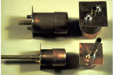
Copper Pipe Bandpass Filters
As used in OCAR to limit non-Ham inputs
"...the dimensions of the helix are so noncritical that a helical beam
antenna is one of the simplest types of antennas it is possible to make."
This statement by the inventor, Dr. John Kraus, points out just one of
the reasons we decided to experiment with helices. The circular
polarization was another reason since it might lead to less multipath
distortion. But what we found was that the antenna was neat looking
yet unfamiliar to most viewers.
Keeping in mind the general parameters of the circumference at about
one wavelength and the spacing at a quarter wavelength, here are the
formulas I used to design helical beam antennas for 904 and1265MHz:
Several helices were built from Kraus' specifications using an 0.06"± aluminum plate, about 12" in diameter, as the groundplane and main structural member. 0.75" to 1.25"PVC pipe and fittings were then glued tightly, through a drilled hole, to the plate and an N connector mounted, all so that the helix centered itself on the ground plane. 7 to 15 turns of 0.25" aluminum tubing were wound first to the correct diameter and then stretched open to the correct spacing. The end of the tubing nearest the groundplane was flattened and drilled to fit over a 4-40 brass machine screw which was filed to fit the N connector's, center solder lug. To this lug was applied Ilsco De Ox compound, on the suggestion of K6HSJ, to prevent oxidation. The tubing was hung from a PVC pipe attached to the groundplane and kept in place by wire ties. My dimensions for the ground plane are a bit shy of an optimum of around 13" diameter, but the antenna seems to perform well and I used the aluminum I happened to have on hand.Other methods are being tried to more securely and accurately attach the tubing to the PVC structural element. Initial measurements indicate very broad bandwidth as suggested by Kraus.
See Glenn Elmore's Garage pagesor his OCAR pages for more detail on use and measurements.
Books by Dr. John Kraus
Antennas
 Dual Section Filter
Copper, inter-digital filters have also been tested.
This page by John Watrous, K6PZB
jwatrous@sonic.net