 |
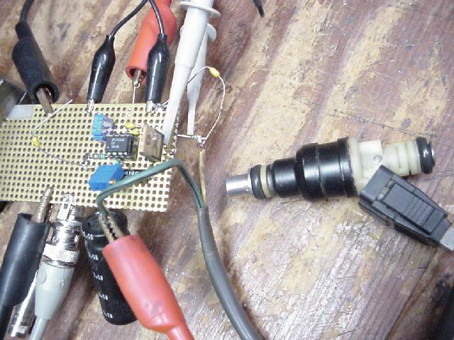
I had some concerns about the injector
drivers. I wanted to make sure that they performed exactly as expected for
both high and low impedance injectors. This design uses the
tried and tested National LM1949
Injector Drive Controller chip. I didn't really expect to see any
problems but if any did exists it would be much easier to fix before
the layout went to copper. I mostly wanted to assure myself
was when the timer timed out on a long open periods with high impedance
injectors that nothing funny happened. As it turned out it was a
good thing that I did check it out, but it wasn't with a high impedance
unit that the problem occurred but with a low impedance injector.
As the controller switched to Hold mode it started to oscillate.
Probably a function of the beta of the TIP102 darlington driver
transistors, or maybe some unexpected inductance in the emitter
circuit. I had an .01uf compensation cap (C302 below) installed as recommended.
This greatly reduce the oscillation but it was definitely still there
as the plots below will show. Adding the 1.96k series resistor
was enough to shift the phase margin enough to stabilize the circuit without any adverse affects on performance.
|
With the current sense resistor set to .1 ohm it makes thing simple to calculate. 100mv
across it equals one amp through the injector. The LM1949 trips into hold mode
when the voltage across the sense resistor reaches 386ma, 3.86 amps in
this case. During hold mode the controller acts like an op-amp
holding the voltage across the sense resistor to 94mv. R300/C300 set the
timer period to just under 5ms. This timer is used during periods
where the current through the injector doesn't reach the 386mv threshold. This can happen during cranking periods where
the battery voltage is too low to get 3.86 amps through the injector
coil. When one TC is reached (4.6ms here) the controller drops
into hold mode. The 51 volt zener (VR300) clamps the maximum
positive voltage excursions to 51 volts. This diode gives the energy stored
in the injector coil some place to go. If it wasn't for stray
leakage this kickback voltage would go to infinity destroying as much
silicon as it could on the way. C302/R320 compensate the op-amp portion of
the controller to maintain stability during hold mode.
We can safely use high impedance injectors with this
driver also. Their typical coil DC resistance is around 14-16
ohms. This means when the controller drops into hold mode, which tries to maintain 940ma through the coil, the
pass transistor will be fully turned on because we can't get the required one amp through
a 15 ohm injector with a 14 volt battery. So this circuit doubles as a straight switch which a high impedance unit needs.
The one caveat is that you probably can't use it in batch modes where more than
one injector is tied together. That .94 amps will get split
between the injectors. Mostly likely if only two high impedance
injectors were tied together that 500ma would be enough current to keep
it open. More than two and I would bet you'd get into trouble.
| These plots show the delay between the trigger edge and the driver transistor turning on. Also note the speed at which the transistor does turn on. These where taken before any modifications to the compensation network. After the series resistance was added there was no change in the slew rate of the collector voltage. |
| ||
| This plot shows the full operation with a low impedance injector. You can see the current build to 3.9 amps and the controller reacting and dropping into hold mode. If you look closely at the voltage across the sense resistor during the hold portion you can see signs of the loops instability. That is not noise but oscillations. |  |
||
| This plot is the same as above except the voltage supplied to the injector has been reduced to 10.8 volts. At this voltage 3.9 amps through the injector can not be achieved. After one TC of the RC timer (~5ms) the controller times out and drops into hold mode. |  |
||
| Things don't look so good when we look at the collector during hold mode. The instability is very obvious. You can also the 51 volt zener diode doing it's job. |  |
||
| Same setup but the scale has been expanded. The oscillations period is around 28.5 kHz. |  |
||
| First tried to stabilize it by adding some more capacitance from the collector to gnd. This plots is with a .01uf cap. Still on the verge of oscillation. |  |
||
| This is with a .1uf from the collector to ground. Still has a little ring but stable after that. Not really the answer because it reduced the bandwidth so much that the turn on/off edges really suffered. The following plots show what I mean. |  |
||
| This is the turn on response of the driver transistor with the .01uf cap from its collector to ground. Refer back to the very first plot on this page and you will see that it only took about 100ns to completely turn on. Response time is six time worse here. |  |
||
| If the .01uf looked bad the .1uf really killed the loop. Close to 2ms to do what should be done in 100ns. |  |
||
| Well after a little bit of head scratching I finally came up with the putting a resistance in series with the compensation cap. The 1.96k resistor shifted the phase enough so that all the instability and tendency to oscillate was killed. Also it had no affect on bandwidth so the turn on/off times of the driver transistor were unaffected. |  |
||
| Looks much better with the improved compensation. Nice sharp edges and no tendencies to oscillate. |  |
||
| The following plots are all with High impedance injectors. This one shows that the driver transistor is turned fully on for the whole period. |  |
||
| Just to make sure that when the timer timed out nothing funny happened. All worked as advertised. |  |
||
| You can see the current rise in the injector coil to its maximum amount based on its DC resistance. |  |
||
| Here I added another injector with the first. You can see that the initial current is twice as much but when the controller timed out the regulated 940ma is split between the two injectors. Probably would hold them open but more than two would definitely be trouble. |  |