Power Supplies - Block A
NOTE: +5VF and +5VRef modified 02/27/05
NOTE: -5VF modified 03/28/05

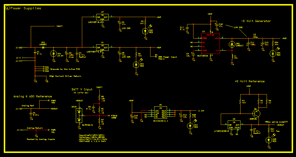
Pretty basic supply setup. CR1 protects negative potentials from entering the supply while the VR1, a
1N6279A 1500 watt Transient Suppressor, protects the regulators from any
high-energy transients. A couple of LM2940
linear low drop out 1A regulators immediately follow. The +5 volt unit feeds the majority of the circuitry along with replacing the +5 volt
regulator on the Axiom PCB. Decided to go this route to assure that both boards came up in unison and that neither supply would be
higher than the other. The +8 volt unit feeds several of the analog op-amps to give them a little more operating head
room. A Maxim MAX735CSA DC-DC converter generates a -5 volt supply used for head
room and some needed offsets. U6, a MC33269D-3.3 regulator,
supplies the +3.3 volts needed for text-to-speech synthesizer circuit.
The +5 volt reference is based on the LT1021DCS8-5
precision reference IC. Q1 is acting as a current pass transistor isolating the reference IC from external loads while increasing the
current handing capabilities. The ADC on the MPC555 will also be referenced to this supply. The series resistance in the collector circuit (R4,R8) are
currently set at 5 ohms (10 ohms each). Been playing with these values somewhat lately. In this configuration at room temperature the LT1021
starves for power when its input gets to about 6.75 volts. This means that the minimum emitter voltage on Q1 has to be 7.45 volts. With an
8 volt supply it takes 110 ma. to get to this minimum voltage. So at 110 ma and 2.45 volts across Q1 this gives us a power dissipation
of 270 mw. This is less than halve its rated maximum power dissipation of 625 mw. and well below its maximum collector current. But because
there is no current limiting a shorted 5 volt reference to ground for any length of time will pop Q1. As an experiment I loaded the supply with a 10 ohm
resistor. This brought the reference to 3 volts (300ma). The transistor was dissipating over a watt at this point in time.

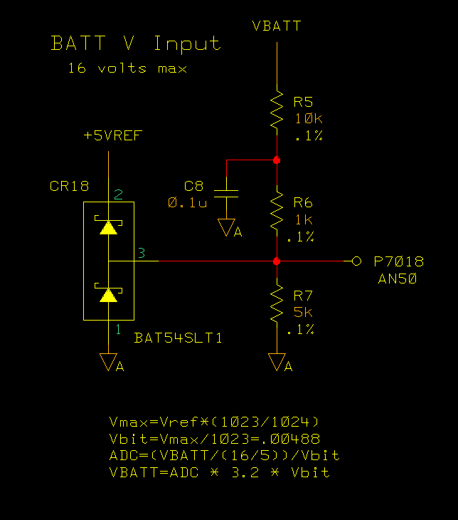
This divider is directly connected the switched battery input to determine the actual voltage of the battery
during operation. The current battery voltage is factored into the injector pulse width calculations to compensate for slower turn-on
times at lower voltages. CR18 is just a little extra protection for the very expensive MPC555 ADC input.


