What I am looking for here is
a way to settle down the closed loop response. I don't mean just
slowing it down because I do want it to acquire the closed loop condition
quickly and to respond smartly to changes in the motor's load. My
feeling is that the loop is over controlling the engine, making changes
to the mixture greater than are needed. An example of this is during
cruise, say around 55-60 mph. I would see the O2 voltage swing back
and forth, as it should, but I could also feel the affect on the motor
as the closed loop fuel modifier changes the injector's pulse width
back and forth chasing the O2 voltage. You could here the tone of
the exhaust change pitch along with the smoothness of the engine and a
slight surging as the closed loop fuel modifier would adjust the mixture
to the motor way too lean then way too rich. True, the average would
be around the target stochiometric AFR, but the loop was way over controlling
to keep it there. The surging may be slightly aggravated in my situation
because my 350 and cam combination does not like excessively lean mixtures.
Also the open exhaust and the fact that most of the time the rear window
on the coupe is down you are really aware of what the motor is doing.
If you haven't studied the code yet maybe a little
background of the key players might be in order here. There are two
major loops running in the code. The first one, with the highest
priority, is the Ignition Trigger handler. Obviously every time an
ignition pulse comes along from the distributor this routine takes over
what ever else is going on at the moment and does its thing. The
ignition handler is responsible for reading the O2 sensor ADC and determining
what direction to adjust the closed loop fuel modifier (L0079) needs to
be moved (of coarse this assumes that all closed loop rules have been met).
If the O2 voltage is below 447 mv then the value of L0079 is adjusted to
increase the mixture, otherwise it will move in a leaner direction.
The value stashed in L0079 is a signed integer that can move a maximum
of +/-16,000 counts. If this value is positive it is subtracted from
the calculated pulse width reducing the AFR, if negative it will make the
mixture richer. A value of 16,000 represents approximately a 20%
change in fuel. The amount that this accumulator (L0079) is changed
by is in L0075. So L0079 is how far the mixture is adjusted
and L0075 is the rate it is adjusted by. The ignition trigger handler
itself doesn't actually apply the value in L0079 to the injector's pulse
width. The is done by the second major routine. This loop waits
till the MAP ADC is read by the Ignition Trigger handler (every ignition
event) then starts processing all the sensor inputs and computes what injector
pulse width and spark angle that the Ignition Trigger routine should use
and apply to the engine. It is this loop that actually determines
if it is ok to go into closed loop, determines the rate (L0075) to modify
the accumulator, and apply what is in the closed loop accumulator (L0079)
to the pulse width that it has just calculated. So in a nut shell
the Ignition Trigger routine determines the direction and applies the rate
modifier (L0075) to the closed loop fuel accumulator (L0079) while the
main calibration loop calculates pulse width, applies the accumulator,
and determines the rate of change.
At first I approached this by attempting to slow
down the accumulator when the O2 error voltage was off its rail, or at
least a somewhat arbitrary point close to the rail, by reducing the rate
value in L0075. I tried several variations of reducing the rate value
as the O2 error voltage approached the nominal center voltage of 447 mv.
It helped slightly but wasn't very effective. The big trouble here
is the the O2 sensor's response is very slow and always lagged well behind
what the fuel accumulator was doing. Even if I completely zeroed
the rate value in L0075 when the O2 voltage was off the rail (say between
800mv and 100mv) it made hardly any difference at all to how far the fuel
accumulator would go. The accumulator value would already be considerably
too far the wrong direction before the O2 error voltage would even begin
to change. So this approach alone wasn't going to do the trick.
Another thing that aggravated the situation was in the way they calculated
the rate of change value in L0075. The magnitude calculated was a
direct function of RPM. The faster the motor turned the larger this
value was. Two things caused this. One was the lookup tables
(at LF554 and LF544) both increased with RPM and the other effect was that
as the motor turned faster the MAP ADC was read more often releasing the
main calibration loop and applying the rate value in L0075 to the accumulator
(L0075) more often. It looks like the O2 sensor's response time is
pretty much fixed (at least at a given operating temperature) so by increasing
the rate of change value, and how often it was applied to the accumulator,
made the situation of over compensating worse the faster the motor turned.
I needed a way to normalize the rate value so that no matter how fast the
motor turned it would modify the accumulator at a fixed rate (time) also.
The rate varied from about 3.3%/sec @ 1500 rpm to 18%/sec @ 4000 RPM.
What I did was come up with a set of values that would normalize the rate
value to RPM. There were originally two lookup tables, one at LF554
that was used when the O2 error voltage is below 447 mv (lean) and the
other at LF544 for when the error voltage was above 447 mv (rich).
What I did was split the difference between the two and pick a point at
2500 RPM to create my new set of values. This works out to 6000 counts/second,
or 7.5%/sec. Seemed like a reasonable starting point. The below
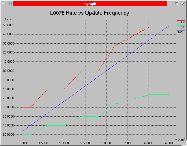
plots show what originally was calculated for L0075 vs RPM.
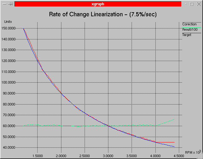
The second plot is of the results with my new set of values. The
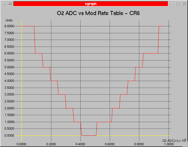
third plot shows the O2 error voltage break points. This is where
the rate value is further modified as the error voltage gets closed to
447 mv.

The first one here shows results of the two original
tables. You can see that rate for when the mixture was lean
is twice as much as for the one if the mixture was rich.
The blue line represents how many times the
rate value (L0075) is being applied to the accumulator value (L0079).
The faster the motor turns the more the ECU would over compensate driving
the accumulator much farther than needed.

This second plots shows what is now being calculated
for the rate value in L0075. The blue
line represents what the output of the calculations should be. The
lookup table only has eight entries so I can't get an exact match, but
you can see by the red line that I got pretty
close. The green line is the effective
results. I was trying for a count of 6000/sec (7.5%/sec) so you can
see that it very close to target.

This last plot shows the breakpoints where the rate modifier in L0075 is further modified when the O2 error voltage starts moving off a rail. The 'Y' unit is a numerator in the scaling of this value: L0075 = L0075 * Y/16. Currently any time the O2 error voltage is above 92 mv and below 828 mv this further scaling is applied to the rate modifier. This wasn't very effective for off idle operation but it really helped the closed loop idle stability.
Well at this point even with the rate modifier being calculated based on time rather than RPM and the little help that the above O2 error voltage vs modification rate table gives me the loop was still over compensating. I didn't want to just slow every thing down because I still wanted the loop to acquire lock quickly. What I finally came up with is a scheme that so far has been working out well. What I do is when the error voltage crosses 447 mv I immediately move the accumulator value in L0079 half way back to the value it had at the last 447 mv crossing of the O2 sensor and then hold off any more modifications to it for a period of time (currently around 300-400 ms). What this does is give the O2 sensor time to catch up with what the motor is actually doing and still allows the loop to acquire lock quickly.
The below plots show some before and after operations. They represent cruise operation around 2500 RPM. Check out the Scaling Page for units explanations.
This is one of my early test runs. The O2 loop
routines are in their stock form at this point in time . You can
see that the fuel is swinging back and forth most of the time around 10%-12%,
and at times closer to 14% to 16%. You could feel and hear the motor
leaning out at the bottom of those dips. Also notice that the O2
error voltage is not really symmetrical. There is more time spent
on the rich side than the lean. As steep as the error voltage transitions
are you can see way that just reducing the rate of change during the transition
period had little affect.
Here are two runs that were taken after I applied all my modifications. You can clearly see that the fuel modification value is much more stable without all those wild swings. The peak-to-peak is much closer to 1%-2% with a much smoother and consistent average. Also notice that the O2 error voltage peaks are not as great and that there is much more activity, at least twice as much, around the 447 mv crossing point than before. No more extreme swings into the excessively lean areas. The motor purrs like a kitten now with no more surging and the exhaust tone is steady. The loop will still acquire lock just as fast as it did before because the rates outside of the capture range are about the same.