 |
Well this is what the new crank trigger input circuit looks like. The input diode limits the pickup's voltage swing of 14 volts to 5 volts. The 2.7k helps pull up the pickup's output to give a better edge. The second diode going to the +5v supply and R23 limits the input voltage going to the op-amp to under one diode drop above Vcc. This is needed to bleed the charge off the input diode created by its capacitance. R22 was reduced to 562 ohms to improve the edge going to the schmitt trigger. At first I removed R28 to decrease the load on the op-amp's output but found that it could not source current well. The resulting slew rate was distorted and had a knee in it.
 |
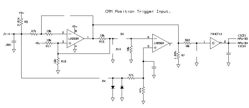
The unused magnetic input circuit re-configured to handle the Hall Effect sensor in the distributor. Will use this path to detect the CAM position to synchronize the injectors. This circuit ended up the same topology as the original distributor input handler with the exception of R8. I reduced this value by a factor of 8 to increase the edge going into the 74HC14-1.
 |
A short Readme file on the setup conditions can be found here.
| This was before
I replaced R28 which helped
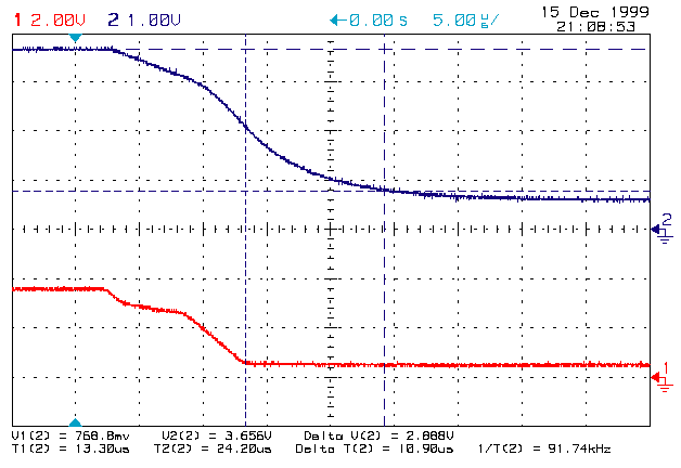
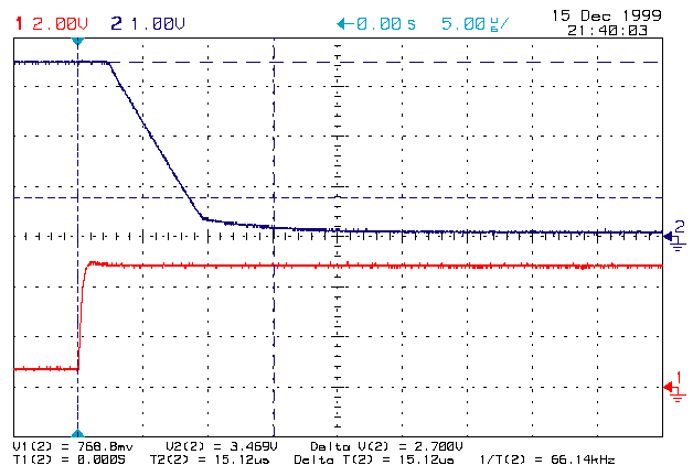
the op-amp's output edge and the coupling resistor was still 4.7k See how slow the edge is. Note the 24us propagation delay. - R28 removed (no pull down)
|
 |
| This is across the 4.7k coupling
resistor.
- R28 removed (no pull down)
|
 |
| This shows how poorly the
LM2904D performed
without the load resistor. - R28 removed (no pull down)
|
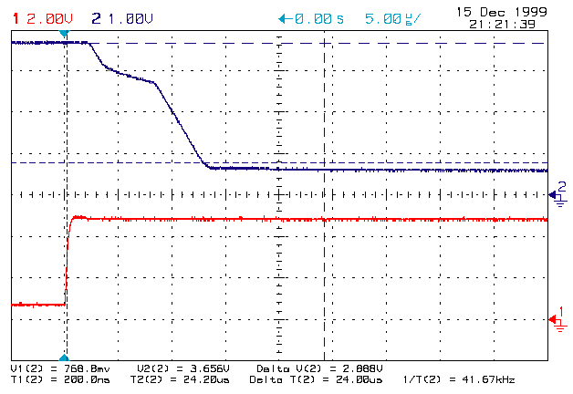 |
| Things are improving with
the addition of the
load resistor. A little better edge. Note the 15us propagation delay (better). - R28 = 562 ohms (892 ohms total)
|
 |
| This across the 4.7k coupling
resistor again.
You can clearly see the RC delay it causes. - R28 = 562 ohms (892 ohms total)
|
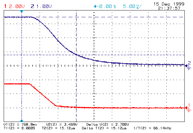 |
| Got a decent slew rate with
the 892 ohm load.
- R28 = 562 ohms (892 ohms total)
|
 |
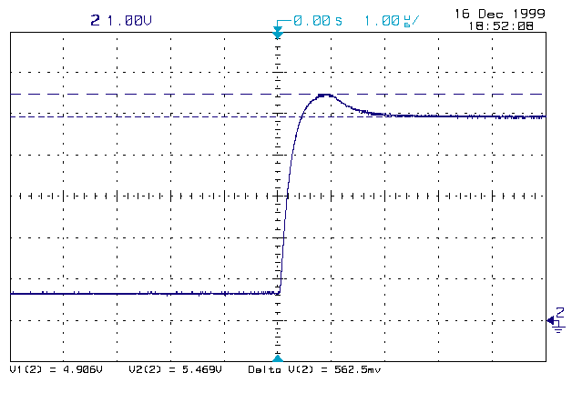
| Looking at the over shoot
caused by the
capacitance of the input diode. R23 and the limiting diode are doing their jobs. - Input = Function Generator
|
 |
| You can see how reducing
the series resistance
has improved the response. The input to the schmitt trigger is almost the same as the output of the op-amp and we still have amble phase margin. - R28 = 562 ohms (892 ohms total)
|
 |
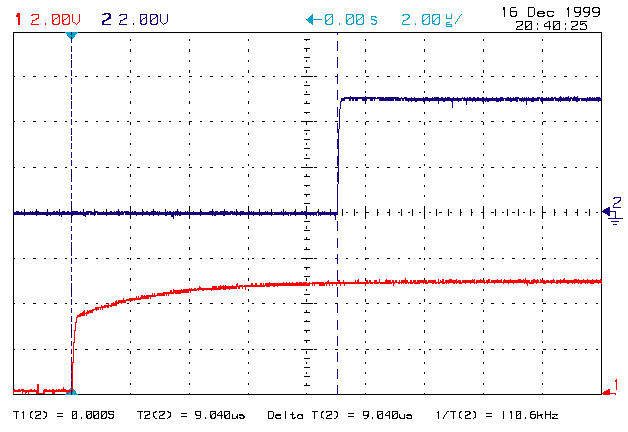
| Here is the total propagation
delay through the
circuit now. We started with 24us and with a few tweaks got it down to 9us. - R28 = 562 ohms (892 ohms total)
|
 |
| Here is a look at the trailing
edge performance.
Not really an issue as it won't be used by the ECM's code any more. - R28 = 562 ohms (892 ohms total)
|
 |
| A look at the total propagation
delay of the
CAM position input circuit. Same as the crank trigger circuit, as it should be. - #1 = Trigger input edge (J1-4)
|
 |
| A look at the unloaded response
of the crank
trigger pickup. You can see that its response is not too bad to about 50% of the supply voltage. After that it takes forever to get to the rail. - Vcc = 14 volts
|
 |
| Here is rise time (of the
first 50%) of the
unloaded pickup. The capacitance of the cable and ECM will slow things down. - Vcc = 14 volts
|
 |
| You can see how things slow
down when the
capacitance of the cable is added. Also at this point the Magnetic Output is still attached. It also loads the square wave output. - Vcc = 14 volts
|
 |
| Same conditions as above.
Cable loading has
no effect this far out. - Vcc = 14 volts
|
 |
| You can see the improvement
to the square
wave output when the magnetic trigger output line is unloaded. When I install it in the car I will leave this line dis-connected at the plug. - Vcc = 14 volts
|
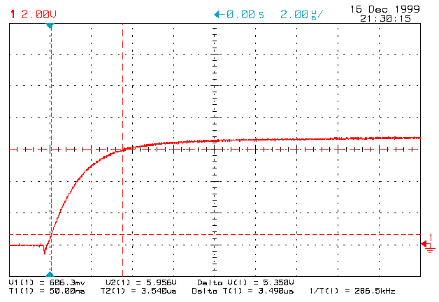 |
| Here is the response when
finally connected to
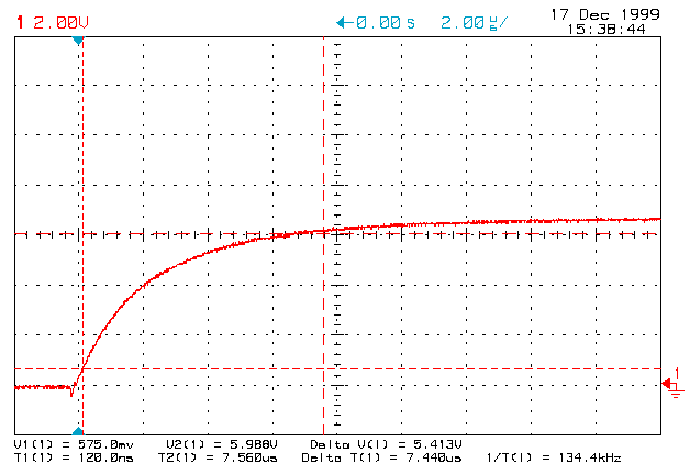
the ECM. I left the .001uf input filter cap in place. Slows things down a bit but also helps filtering out high frequency noise that may cause false triggering. - Vcc = 14 volts
|
 |
| Here is the relationship
between the trigger
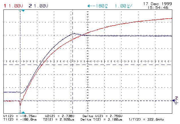
signal as it enters the ECM and the input to to LM2904D op-amp. V2 is the threshold when the op-amp will react. - Vcc = 14 volts
|
 |
| Well here we have the whole
thing from the
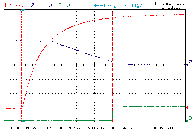
pickups edge to the 74HC14 Schmitt trigger's edge. Total propagation delay: 18us - Vcc = 14 volts
|
 |