You are viewing a document last Modified on
so be sure to
refresh your browser to be sure there isn't a newer version !
CAT5 cable routing, Scattering &
Shadowing
A probe antenna is categorically different from a matched antenna in that
no power is extracted from an incident wave. Although no power
is extracted, the presence of such a probe element does deform the
nearby electric field of an incident wave which is to be
received. Put another way, the presence of conductive material
causes scattering. For both matched and
probe antenna types there is a region of influence for such an
element generally called an aperture. For best operation it is important
to keep this region clear of conductor. See Antennas, John
Kraus, W8JK,Second Edition, Ch2. sec 2-14
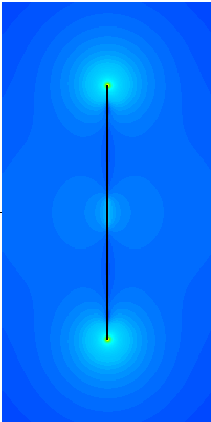
Here is a 4NEC2 rendering of the field strength along the axis of a
dipole. This is not total field but rather the field parallel with the
axis of the dipole and with the far-field polarization. Notice that the
strongest radiative field is in the volume of space at and just beyond the
tip. This is the region where Bremsstrahlung-like bound-free acceleration
occurs which can, perhaps, be understood as the mechanism for conversion
of antenna current into far-field radiation. But whatever the
interpretation is, it is desirable to keep other sources of bound or free
charge away from it in order not to disturb it. It is important to
keep the CAT5 cable away from it.
For the SAS use case, induced current in the CAT5 can produce
re-radiation that counters the impinging electric field near it and cast a
shadow that can overlap the probe's aperture. Rerouting the CAT5 or
reducing current within it can reduce this interaction. Empirical
measurements have shown that a few percent degradation in WSPR spots is
produced when the CAT5 simply exits vertically, parallel and close to the
dipole (CAT5 90) but not far enough away to escape the shadowing as
compared to spots produced when the CAT5 comes away at an angle (CAT5
45). Compare the e-field magnitudes at the dipole tips,
graphically represented in the z-axis plots above. Sight rerouting seems
to be enough to cause the interaction to become
negligible. For this reason, a revised mounting
technique different from a closely parallel one is being followed whenever
possible.
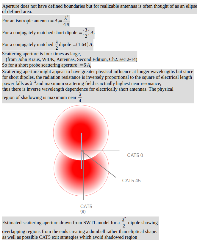
The sketch on the left below shows rather the reverse of the
SAS use case. In it a scattering dipole is shadowing a CAT5 90
'monopole' rather than the other way around. Though the areas
are to scale, the shape and field intensity distribution
depictions are not intended to provide precise information but only a
general impression of the situation when a sensing antenna is shadowed by
a nearby scatterer. In this sketch, possible routes for the
CAT5 'antenna' that might be used to keep it sufficiently far away from
the probe "shadow" are shown. These are ways the interaction between
the CAT5 and the probe may be minimized.
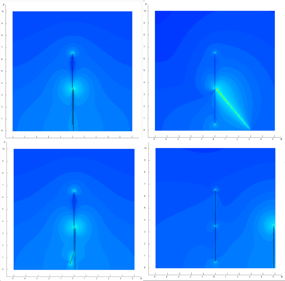
NEC2 (4NEC2) visualizations of the resulting vertical e-fields produced by
an incident electric field are shown below to the right. These are
with a uniform linearly polarized incident field and above a MiniNEC
ground. In each case the test frequency is that where the CAT5is a quarter
wave length, where it has highest Q and produces the largest fields. The
bottom of the CAT5 is directly connected to the 'ground', which produces
higher current and more scattering than an actual use case where a
continuation of the CAT5 cable continuing a considerable distance to
the ShackBoard location will have non-zero impedance.
An idea of the degree of scattering may be obtained by comparing the
e-field intensity near the tips of the dipole for the CAT5 90, CAT5 45
cases and the"bell-bottom" case where the lower portion of the lower
mono-pole element is simply moved away from the CAT5 at an angle. These
strategies are suggested by SWTL theory which indicates (see
A
New Antenna Model)
- no significant TEM coupling for these geometries between the
CAT5 and monopole element far from the tips. This is maintained if the
smallest conductor of a parallel conductor line is kept 100 diameters
away from the other so that the line is TM only.
- the aperture associated with radiation is mostly around and beyond
the tip of the element
The fourth plot at the bottom right shows the mast moved 4.9m away which
also seems "far enough".
Though of use only over a limited frequency range it may be that
ferrite chokes or lossy beads placed on the CAT5 line can also be
used to further reduce the shadowing effect. This has not yet
been investigated.