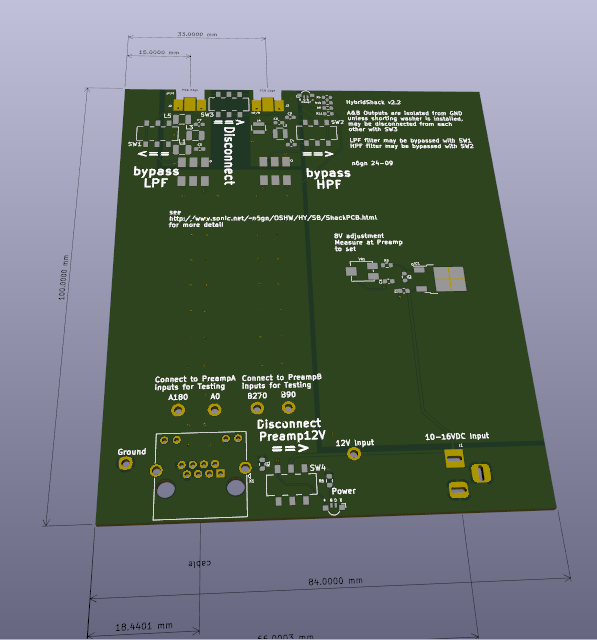
Shack Board v1
This v1 Shack Board can provide power for PreampA, PreampB and
SAPreamps as well as interface from each of their outputs.
However the interface is passive by way of transformers and while
quiet does not produce the common mode rejection of the later, v2
design. This design contains a diplexer which allows combining two
different antenna/preamplifier units to create a Hybrid antenna
system. It will generally not be used except for this specific case.
Power for the supported preamplifiers is provided from the input
10-16 VDC regulated with an adjustable LDO to produce 8V at the
preamp, after any voltage drop in the intervening CAT5 cable
Provides power and interface for
all preamps; PreampA, PreampB & SAPreamp.
Receives one or two pairs of CAT5
RF from an associated preamplifier
Preamp input buffer bias switch to
verify system common mode performance
Completely passive. approximately 0
dB conversion gainfrom 100 ohm CAT5 to 50 ohm output
may also be used for initial
testing of Preamps, Junction Box and cables.
Front Connections:
SMA: 2 one for each of A and B CAT5
lines
Rear Connections:
2.1mm barrel connector for power
RJ45 for CAT5 to preamp(s)
External supply voltage 10-16 VDC, current depends upon
Preamp selection
Double-sided, 4-layer, silk-screen PCBs
This PCB may also be used for initial testing of Preamps, Junction Box
and cables.
Features
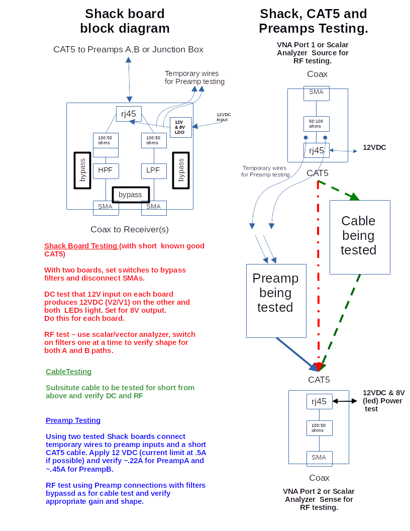
Testing
There are also switches on the PCB to allow verifying proper preamp
performance.
Since assembled PCBs must be ordered with minimum quantity = 2 ,
this makes a good arrangement for testing. Using each of two PCBs as a
simple 50 Ohm <==> 100 balanced line adapter lets transmission
through a length cable be measured. Applying power to either of the
interconnected boards also allows checking power function of each
board.
DC tests can be performed with a multimeter for power supplies. For
RF testing a broadband measurement using a scalar or network analyzer
is a very good method. This may be done with a TinySA
or nanoVNA. Loss through the
system during a two-Shack board test should be near 0 dB. Typically
CAT5 cable loss should be about 3 dB/30m at 30 MHz.
Initial version of the Shack Board with diplexer included.
Use
In addition to its main function of supplying power to Preamps and receiving differential RF over CAT5 cable and delivering the filtered/combined results to a receiver, this board also has a switch to disconnect the 12V supply from the input circuits of a probe preamplifier while leaving output stages operative. This is useful for identifying common mode and other unwanted noise ingress apart from the intended balanced antenna.

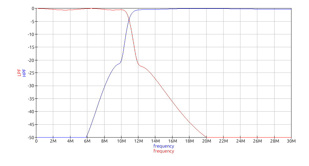
Diplexer/combiner frequency response:
|
||||
Item Description |
Provider |
Source Code |
Notes |
Approximate Material Cost(excludes setup fees and shipping) |
Assembled ShackPCB PCB |
Download ShackPCBv1 Kit Files==> JLCPCB |
Download ShackPCBv1 Source Files==> KiCad |
Added Preamp12V/LED and shorting
relay switches |
US$ |
38x88x100mm Clam Shell Enclosure |
eBay |
Other sources possible. Enclosure needs to accept 84mm wide PCB. | US$12 |
|
38x88mm ShackPCB Front Panel |
Download ShackPCBv1 Front Panel Kit Files |
Download ShackPCBv1 Front Panel Source Files |
Select 'Aluminum" when ordering.
These are panels only no components. |
US$1 |
38x88mm ShackPCB Rear Panel |
Download ShackPCBv1 Rear Panel Kit Files |
Download ShackPCBv1 Rear Panel Source Files |
Select 'Aluminum" when ordering. These are panels only no components. | US$1 |