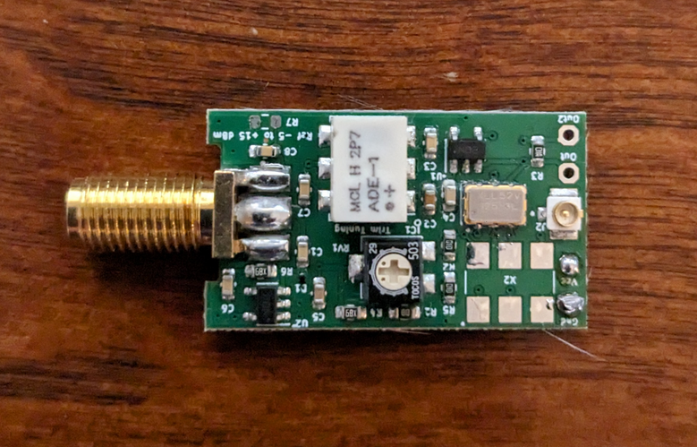
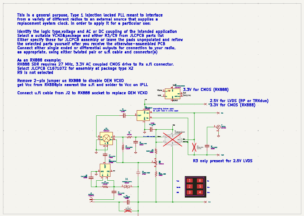
This is an injection locked
PLL for the TRXduo, Red Pitaya and other SDRs or
single-master-oscillator amateur radios including both SDR and
superhet multimode transceivers. It is one that I think has some
advantages including generality and automatic switching between
undisciplined/internal and disciplined/external reference operation
that can provide sub-ppb frequency accuracy and low spurious and
spectral noise power density clocks for ADCs and LOs for LF through
microwave communications.
It is in the form of an add-on PCB
that can mount insideA TRXduo or Red Pitaya using a Type I PLL and
VCXO to replace the OEM clock. In the case of some radios,
Shown below for the TRXduo.
For
better quick viewing of the design, download the Source
file from the Material
List below , unzip it and drop the .sch or .pcb file onto kicanvas from a web browser.
[Caution]
Many installations will require internal soldering
probably in an SMD environment.
This may beyond what many should choose to attempt !
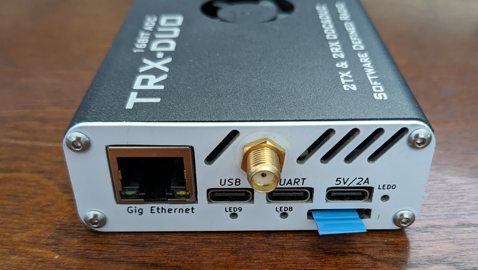
In the TRXduo it connects via 4 leads to get Vcc/Gnd and LVDS outputs at the original TCXO's pads. You can see it here at the left mounted inside a TRXduo
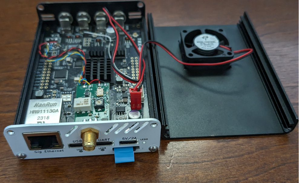
The four connections are visible as two pairs of wire wrap conductor
connected at the OEM TCXO at the upper right. The ground connection
spans 3 pads to disable that oscillator which is replaced by the PLL.
The white conductor is just a PTT line used to control a transverter or
other equipment.
Frequency trimming is provided by the potentiometer on the PCB which puts unlocked/undisciplined operation close to 125.0000 MHz. When an external 125 MHz reference signal of -15 to +15 dBm is injected at the SMA, the PLL "turns on" to phase lock the VCXO to the external reference. It is also possible to use a 1/5th frequency, 25 MHz, external reference with reduced capture range. Measured spectral noise power density is more than adequate for any HF communications from FST4W to >10 kHz information bandwidths. The external input terminal is DC blocked and completely isolated to greatly reduce common mode currents. It presents 50 ohm impedance to the driving external reference so that when normal 50 ohm coaxial cable is used the shape of the reference signal is maintained.
I don't have a Red Pitaya to demonstrate it on but circuits are essentially identical so I would expect identical performance. This should also work to provide GNSS or local OCXO/Rubidium frequency referencing for QDX (25 MHz VCXO) and other radios as well simply by selecting an appropriate VCXO. Quite a variety of frequencies and output types, PECL, LVDS and CMOS to accommodate a variety of SDR clocks seem to be available at quite low prices. Renesas offers > 900 varieties with different Vcc and output types available at many common frequencies.
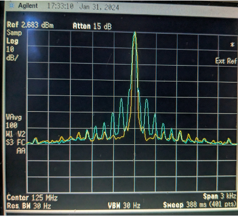
Here's a measurement made with the PCB lying on the bench, with leads strewn around without lock (cyan) and with external 125 MHz GNSS disciplining (yellow). One can see the ~3 kHz PLL bandwidth cleaning up some low level mains related spurs present on the unlocked VCXO (blue).

|
||||
Item Description |
Provider |
Source Code |
Notes |
Approximate Material Cost(excludes setup fees and shipping) |
Assembled IPLL PCB |
Download IPLL Kit Files |
Download IPLL Source Files |
Wait to build. Plan to separate for different end uses.... |
US$15 |
| u.fl cable for RX888 use | Amazon | 2" cables are available but make it difficult to slide PCB in/out | ||
Donation © 2023 n6gn
