This is a 2019 Design for an antenna switch for the KiwiSDR. It was originally done in Eagle rather than KiCad and was for a PCB only with assembly done after receipt of the raw board. Though the design has been ported to KiCad, if the PCB is to be assembled by JLCPCB parts selection and JLCPCB part numbers will need to be specified.
An Antenna Switch for the KiwiSDR
I have recently designed and built an antenna switch for use with the KiwiSDR and its antenna switch extension. I took on this project because I wanted a convenient way to compare results from a variety of antennas, particularly several different broadband active antennas I’ve been developing, both at my home location as well as for a remote site I use for some of these comparisons. This note describes my progress as of March 2019. I’m offering it in the event that it may be of interest and provide help to others who might have similar uses.In recent years I have been using WSPR as a tool for
both examining propagation mechanisms, as it was originally
intended, and also for examining amateur radio station performance
and better understanding antennas. Although I have been transmitting
on WSPR from LF through the 23 cm amateur band as part of these
studies, I’ve become interested in the problem of minimizing receive
system noise floor. I’ve been desiring to reach as close as I could
to the propagated noise floor on every amateur band since it is this
floor that sets the ultimate limit for receive sensitivity. These
efforts have led me to believe that the vast majority of amateur
stations, certainly those below the UHF bands, are not operating
down to this limit.
WSPR has been a very useful tool for examining noise
since there is a large base of sites continuously reporting
signal/noise ratio (SNR) from a large number of representative
amateur stations worldwide, together generating a large amount of
data which can be analyzed.
Examination of the parity among stations which both transmit
and receive on the WSPR network have led to new insights. Some
special spots, such as those from very high altitude WSPR-equipped
balloon transmitters have enabled what are effectively
far-field antenna range measurements of stations and noise floors.
When I discovered the excellent work that John Seamons
and others have done in the KiwiSDR project I was almost immediately
attracted to it and quickly discovered the usefulness of the KiwiSDR
as a tool for measuring and better understanding noise at amateur
stations as well as antennas and propagation in general. In
particular, the spectrum analysis capability of this receiver,
available data in real time from a large number of receivers
operating worldwide allowed additional insight into station
performance, noise and its limitations. As I spent a considerable
part of my working career designing and producing spectrum analyzers
this capability of the KiwiSDR particularly attracted me to it as a
platform.
While studying noise and ways to achieve low noise
floors in the amateur bands I’ve been interested not only in the
instrumentation but also in the antennas used as “probes” used to
measure it. The KiwiSDR encouraged me to seek an effective broadband
antenna, one that could work well from VLF through HF, as a tool. A
prototype design of a small symmetric active antenna I first tried,
a dipole, was constructed and used. Bob Dildine,,W6SFH, (SK) wrote
an article describing that prototype in September 2017 QST. Since
then I have built a number of different antennas and preamplifiers,
both active electric dipole and magnetic loop designs as well as
more traditional antennas passive antennas such as dipoles and
monopoles.
In studying noise sources and in particular the
coupling of these sources to the KiwiSDR I’ve come to realize that
one of the dominant coupling mechanisms of signals that degrade
receiver noise floor is via common-mode signals. These can exist
almost everywhere in the system; they exist on the antenna itself,
within ground systems, on the feedline and other connections to the
antenna and through the KiwiSDR itself. I’m presently of the opinion
that for most amateur stations and even most KiwiSDRs that the
dominant source of unnecessary SNR degradation, QRN and QRM, is due
to common mode currents. Near-field coupling to a variety of types
of local sources, interference which is attenuated as a function of
distance faster than the inverse-square field of a radiated plane
wave emanating from a distant source dominates a majority of amateur
stations.
Although resignation to the existence of “all those
noisy digital devices” and the mindset that interference has to be
accepted seems to be the prevalent wisdom within the hobby, I’ve
found that this is not the case. I have come to believe that the
vast majority of amateur receive systems are not limited by either
propagated noise, which would be the desired condition, or by
radiated noise from local interferers, as is commonly espoused, but
by coupling to near-field sources and in particular common mode
noise. Designing and building an Antenna Switch for the KiwiSDR has
been a part of studying these sources, building better antennas and
extending my effort to create a broadband LF-HF receive system - one
limited by propagated noise.
How Good Does an Antenna Switch Need to Be?
In using and measuring the KiwiSDR I found it to have fairly good performance in general, including rather good power supply rejection ratio (PSRR). Even a large noise and signal superimposed on the PS input of the KiwiSDR, for example a .2 V peak-peak at 160 kHz from a 12V-to-5V buck converter, results in relatively small amounts of QRM at the fundamental and its harmonics. This amounts to on the order of 60 dB or more PSRR for the receiving system. But I also found that common mode current from a well-isolated source, injected on a line or lines at the PS, LAN end of a KiwiSDR enclosed in its metal case and having a return path through the “ground” at the SMA end of the receiver reveals on the order of only 70 dB rejection. An isolated 0 dBm 50 ohm source produces around an - 73dBm/S9 signal within the KiwiSDR even though that current flows only through “grounds”. It appears that current paths through the PCB metalization are such that IR drop generates signal that appears as an input to the KiwiSDR’s preamplifier.Knowing this limitation, when I started designing an
antenna switch I knew from the beginning that it would have to be an
isolating switch. It is necessary to reduce common mode currents if
the result was not to degrade the noise floor and sensitivity of the
receive system. Since the KiwiSDR has a native noise floor, due to
the 24 bit resolution of the information channel, of about -157
dBm/(1 Hz) this isolation would ideally allow no more than about the
equivalent of a 80 dBm interfering signal generating CM current if
WSPR signals were not to be compromised. Estimating and equating
this isolation goal in the context of unknown source and load
impedances for potential common modes coming in and going out of the
KiwiSDR cables and lines is difficult. It’s further aggravated by
the uncertainty of coupled interference levels but since it isn’t
uncommon to see -20 dBm signals on these lines which can exhibit
several hundred ohm impedance it would seem that 100 dB of isolation
could be useful. Achieving this would imply a series impedance well
above 1 Mohm - a few femtofarads at 30 MHz! It became obvious that
complete elimination of CM current induced noise was more than I was
going to be able achieve for an antenna switch operating over LF to
HF but I decided to try to do my best at designing and constructing
the best isolating antenna switch I could anyway. That process
continues to this day.
My original thought for the switch design and the way I
configured the first version was to replace the aluminum end plate
on the antenna end of the KiwiSDR enclosure with a PCB. That design
provided complete separation of the KiwiSDR enclosure and SMA
antenna shield (note that these are notequipotential, as described
above) from the incoming antenna lines and grounds. Although I
wanted the switch to work well over the entire KiwiSDR range, say 10
kHz to 30 MHz, I used a small SMD transformer having low inter-turn
capacitance. Even lower coupling between windings and more isolation
is possible with different transformers but I wanted to maintain
good performance down to VLF and these transformers were not
specified to operate at VLF.
The switch is controlled by information from the KiwiSDR
Antenna Switch Extension and come from using the BeagleBones
GPIO pins that have been made available as an option for the switch
extension. This extension with the GPIO option was compiled into a
running KiwiSDR and control function verified. Within the switch, I
used opto-isolators with < 1 pf coupling to connect to the switch
control circuitry. I used opto-isolators again to enable couple of
control lines for use when the switch was selecting an
LZ1AQ dipole/loop antenna system.
Since I was aware of the extreme requirements for
isolation and sensitivity of the system yet wanted the flexibility
of software configurability for both antenna switch and control
lines, I decide to use a PIC controller but to arrange it to have it
respond only to control line changes and for the CPU to run at a low
clock speed and to “sleep” when not actively switching antennas.
Along with the use of latching relays for switching I was able to
eliminate any noise or signals that might otherwise be produced by
the controller.
To optimize this switch for use with the KiwiSDR I
included the provision for common-input attenuation and filtering.
An ideal antenna switch needs to not only deliver the input from the
antenna (ideally limited by propagated noise levels) but might also
protect the KiwiSDR from signal levels that would exceed the
approximately 14 dBm instantaneous input limit which would cause the
ADC to exceed the top of its range. Hard limits, such as those that
are provided by protection diodes or other limiting produce
distortion which is very undesirable. While I’ve had good success
with combinations of high-pass filters and attenuators, recently
I’ve been using notches and band-stop filters to limit individual
strong signals at particular frequencies while not degrading the
sensitivity and noise figure over large bandwidths. Since this sort
of pre-conditioning is largely locale dependent and since I wasn’t
sure I’d arrived at a the best solution, to make the switch widely
usable I added the provision for a daughter-board which can contain
environment-specific filtering circuits.
The following figure shows the schematic of the present
version of the switch:
For better viewing of the design, download the Kit file from the Material List below , unzip it and drop the .sch or .pcb file onto kicanvas from a web browser.

From the schematic it can be seen that there is no DC
path between the KiwiSDR side and the antenna side of the switch.
Only the coupling through the opto-isolator and the broad band
isolation transformer and any through-the-air self capacitance
coupling of the whole assembly offer a path for common mode
currents.
Although the first version of this switch was designed
as a replacement for the aluminum end plate on the antenna end of
the KiwiSDR enclosure, because of the difficulty of eliminating any
PCB-to- KiwiSDR coupling and in appreciation of the enclosure
design, which John Seamons indicated took significant effort, in
newer versions of the switch I have added the board on insulating
stand-offs instead. Holes for the antenna input and GPS antenna
cables were provided in the switch PCB. This arrangement provides
flexibility and a maximum “hands-off” approach while keeping the
combination receiver+switch contained to a small volume and cables
short, further minimizing the opportunity for ingress of unwanted
signals.
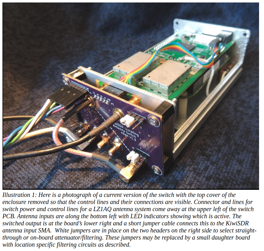
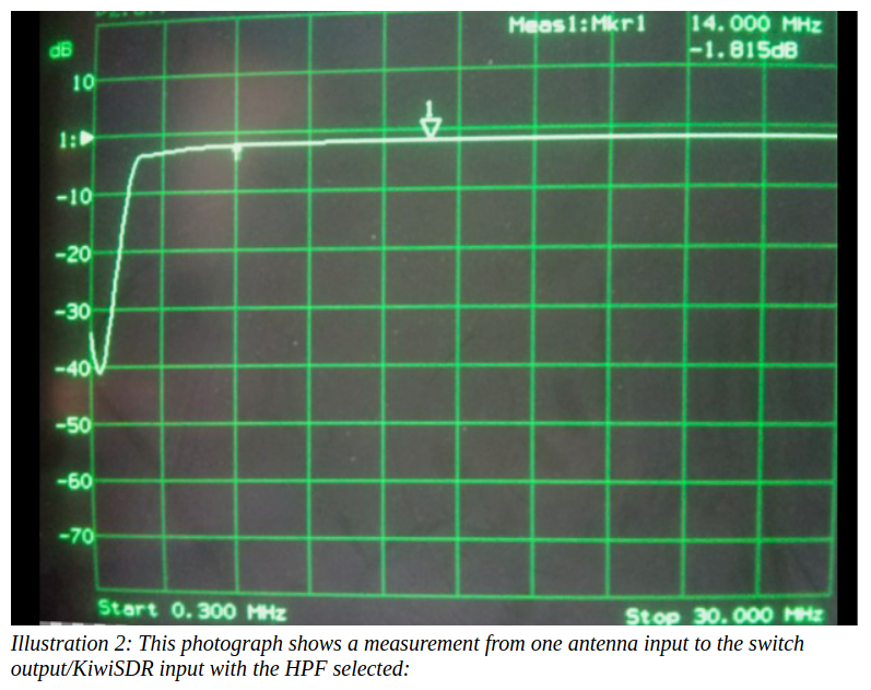
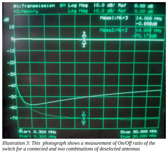
The current results are shown in the following
photographs.

Like my other projects, this one never seems to be
finished. I’ve used the switch for a while now and the current
version seems about ready for deployment at a remote site but there
still exist changes which I think could make it better.
I think a switch of this design may be useful to other
KiwiSDR owners, however, I don’t personally have desire to
manufacture and support such use. Other projects consume my interest
and time but if someone is interested in themselves building one of
these for their own use, please contact me for the present
schematics, PCB layout (Eagle PCB software format) and Microchip PIC
code for compilation.
Glenn Elmore n6gn@sonic.net
March 2019
Fort Collins, Colorado, USA
March 2019
Fort Collins, Colorado, USA
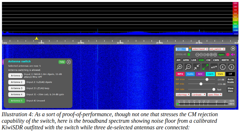
Illustration 4: As a sort of proof-of-performance,
though not one that stresses the CM rejection capability of the
switch, here is the broadband spectrum showing noise floor from a
calibrated KiwiSDR outfitted with the switch while three de-selected
antennas are connected:
|
||||
Item Description |
Provider |
Source Code |
Notes |
Approximate Material Cost(excludes setup fees and shipping) |
UNAssembled Antenna Switch PCB |
Download PCB Kit Files |
Download PCB Source Files |
*This is a KiCad design ported from an Eagle design for ONLY a raw PCB. Parts selection must be done if this is to be assembled by JLCPCB | US$not much |
FirmwareCode you will need to program the CPU |
||||
| PIC Code |
Download PIC HEX File |
Download
PIC Source Code
|
||


