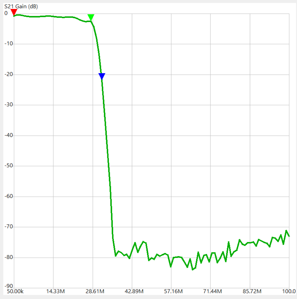
This stop band provides a great deal of rejection of >32MHz signals
and noise that might otherwise alias into the upper HF band and compromise
received SNR for any SDR sampled at a ~60Msps rate.
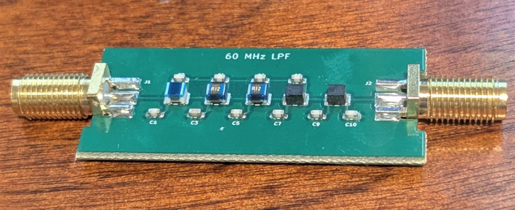
It's reasonable to expect that one fabricated at JLCPCB will perform
about the same.
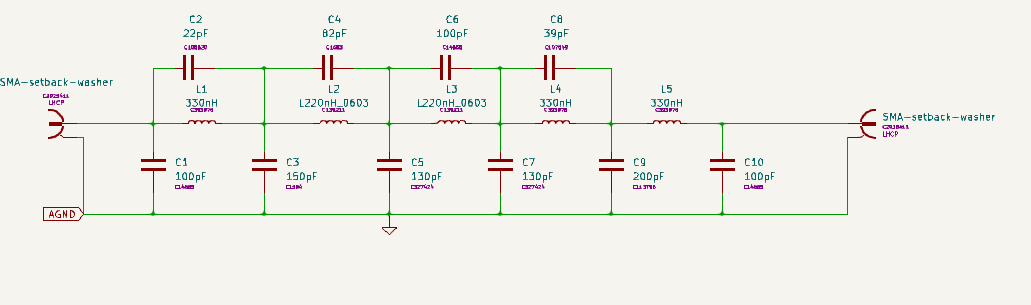
The PCB looks the same as the 60 MHz LPF but has different component
values:
Of most importance in maintaining performance is the Q, the series
resistance of the inductors. If different components are selected,
either due to availability problems or to move the corner frequency of
the filter, be sure to use quality RF inductors rather than lower Q
'power supply' parts. Series resistance of less than one ohm is
desirable to maintain low insertion loss and sharp corner.
For better quick
viewing of the design, download the Kit
file from the Source Link
below, unzip it and drop the .sch or .pcb file onto kicanvas
from
a web browser.
-
Material List
-
What you will need to build this hardware
|
Assembled 30 MHz LPF PCB
|
|
|
Not yet tested from PCB fabricated
by JLCPCB
|