GPSDO & 10 MHz Disciplined Frequency Reference
Features
-
GPS or external 10 MHz disciplined frequency reference
-
Typically better than .1 ppb, .00000001% accuracy and stability
-
Web Interface
-
Provides 2 configurable user outputs, typically 10/25/27 MHz and master clock for HF transceiver or SDR
-
Common SDR and HF transceiver Frequency presets
-
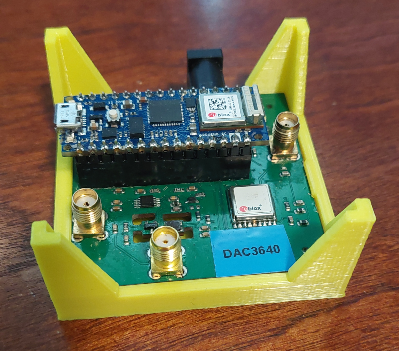
Connections
- SMA: GNSS Antenna or External 10 MHz reference
- SMA:10 MHz standard ouput
- SMA:User Selectable output ~2 kHz to 160 MHz
- 2.1mm power barrel connector
-
Recommended supply 7-14VDC @ ~100 mA
-
Four-layer, through-hole plated, silk-screen printed PCBs
-
Optional plastic holder
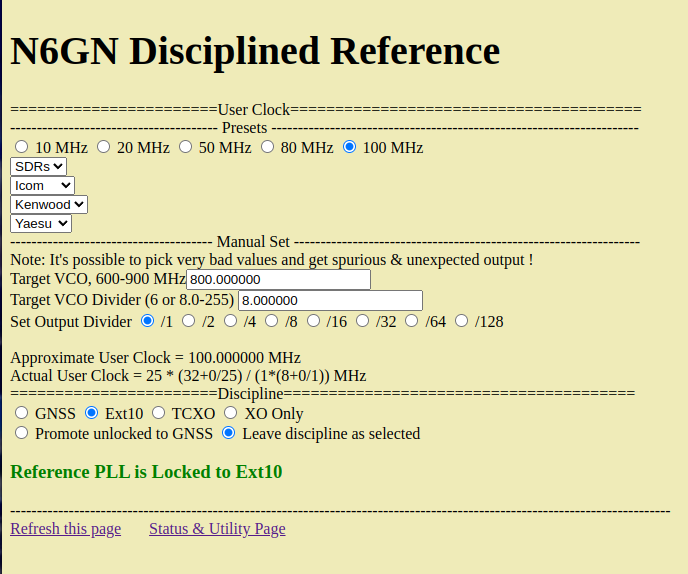
Example Web Interface
;
Operation
Early versions of this Reference that board I've sent out are definitely prototypes. While I think that the hardware itself is capable of working decently, as always, the firmware and user interface is a never-ending task. Make sure you have loaded recent .bin code as this will (hopefully) give you better performance. BACK UP YOUR WORKING FIRMWARE BEFORE INSTALLING ANOTHER VERSION !
Be sure to power this board from an adequate power supply. It will not run properly on USB power alone. Internally the design requires a 4V reference which is only supplied by an external supply. Although the CPU itself can operate from the USB connection. the WFI interface and these circuits cannot.
I also suggest that you arrange to have the Arduino IDE installed locally to make it easy to connect with a serial port (though PuTTY or similar will work) and especially so that you can reconfigure the IoT33 with local SSID:password settings. See 'Uploading New Firmware' below. The IDE tools also provide access to upload and download/save firmware.
Please see This Interface Document to access and configure a Reference to your local situation.
The 'page refresh' selection at the bottom of the main web page
may be helpful. One reason for this is that the Lock Detect may
not be properly indicated and disciplining, either by GPS external
10 MHz input may appear to not to be
working when in fact it is. PLL loop bandwidth is low and it takes
time for lock to be achieved. Perhaps future code releases will
improve this. When using GNSS referencing it may take >10
minutes for adequate, quality satellite connections exist, perhaps
particularly after the unit has changed location (not sure about
this). There is no data storage apart from what the GNSS module
provides so all the necessary data needs to be rebuilt at restart.
Until there is good satellite data lock may not be
achievable. Using the Ext10 MHz lock should be available
immediately.
The board need not be mounted but I have designed a 3D printed
plastic holder that helps protect it and also allows the addition
of some foam padding above and below the crystal oscillator area
to reduce the tuning by room drafts. This is somewhat subtle and
probably not necessary for many uses but does help performance. It
is an adjunct to the thermal island the crystal and TCXO
temperature sensor already sit on. A proper Freq v Temp tuning
curve still needs to be implemented to further improve
non-disciplined mode. This could actually be done with a
self-calibration algorithm but doesn't seem to important since
most operation will be GNSS or Ext10 referenced.
Upon first use of the board I suggest using the Serial Monitor in the Arduino IDE to localize the unit. This means using the serial interface to setup local SSID:PASSWORD so that web access is available. T If it hasn't already been done, the 'dacnom' setting from the Status & Utiity page should then be used in XO mode to place the free-running frequency as close as possible to correct, e.g. 1ppm or setting should be possible, though less accuracy should also work.
If 'Autopromote' is the default startup condition, unselect it, se,lect 'TCXO' and save the state with 'A' from the serial terminal, then restart. This should get you connected to your WiFi Internet connection in TCXO mode the next time you power cycle or restart the unit. Go to the Utility page and use the 'dacnom' field to find a setting that puts either the Clock1 or User Clock output selected as close to correct as you can. Doing this makes it easier for the PLL to quickly acquire GNSS or Ext10 lock once those signals are present. Once again save this value with 'A' from the terminal window so that it will restart in the desired condition.
If you are going to use GNSS mode, attach a antenna or other GNSS RF source. Wait a few minutesfor the GNSS module to acquire some satellites (it does a cold start every time since there's no battery or supercapacitor backup so it may take 10-15 minutes to get good coverage) and select 'GNSSDO'. The Status&Utility page, should show a list of acquired satellites. Normally you might see 30-40 satellites from GPS, Galileo, Beidou systems reported. At this point switching to 'GNSS' should produce lock, though it may require a page refresh to see it correctly reported.
If you are using a local 10 MHz standard of ~+10 dBm instead of GNSS connect it to the same SMA connector as for GNSSDO and select 'Ext10' after setting the 'dacnom' as above. No waiting should be required and perhaps after refreshing the page you should see an indication of 'Locked' on the Status&Utility page as well as on the home page.
Charge Pump Current and PFD divide numbers can be adjusted to improve the trade off between PLL bandwidth, lock acquisition and spectral purity and saved to the power-on state. This area of FW needs additional work as does the method for determining satellite 'quality'.
There are still many improvements that need to be made so a little patience and experimenting may be required to achieve desired results. You may also come across great ideas for improvement, if so please pass them along.
If there are any questions, please ask and I will try to post any answers that might be relevant to others on this site. Also, please let me know of enhancements and changes that would makie it better.
Uploading New Firmware
From time to time there may be new firmware for this device. To upload this to your Reference Board see the
Here is the 'release' version of code, current as of 26 Oct 2023 . BACK UP YOUR WORKING FIRMWARE BEFORE INSTALLING ANOTHER VERSION !
RE2.5base0x61.ino.bin non-standard DAC versionAs of 27 Oct 2023, I expect the above code to be the last that I will release. New sources of HW and/or code may soon be available.
Setup
To setup the device for first use, see the following document:
Schematic and PCB Description
It's not particularly complicated or interesting but here's a schematic
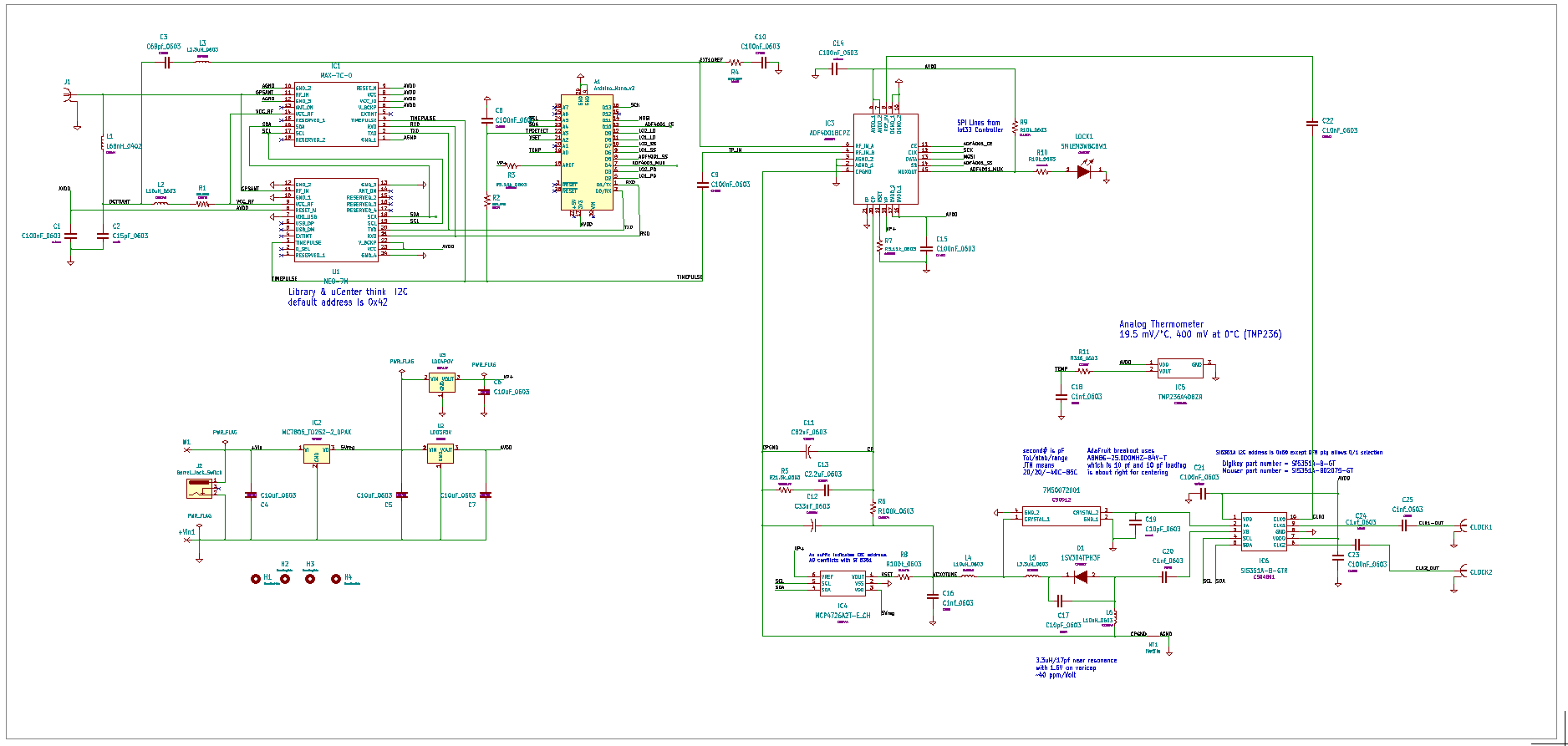 .
.
much lower in even moderate volume.
|
Raw PCBs |
$7.50 |
|
pre-ordered IoT,GNSS.. |
$250 |
|
Components, assembly in China |
$19 |
|
One Time Costs independent of qty. e.g. stencil, fixturing, ext parts, shipping from China |
$51 |
|
per board cost in qty. = 5 |
$66 |
| Final Assembly and Test | 3 hours |
|
Shipping to US |
$10.95 |
|
Shipping to Europe |
$17.50 |
per-board cost might be reduced by using Chinese GNSS (-$16) changing CPU (-$16) with Web server (-$4) , and of course by increasing volume.
Donations Accepted, see HW menu/home page