PART 17
DOCUMENTATIONContents:
Documentation - Access ---- Adding Documentation Content ---- Modifying Documentation Content ---- Modifying Documentation Symbols to Create your Own ---- Customizing and Tricks
|
|
PART 17 DOCUMENTATIONContents: Documentation - Access ---- Adding Documentation Content ---- Modifying Documentation Content ---- Modifying Documentation Symbols to Create your Own ---- Customizing and Tricks |
| 1Documentation - Access | 1-17 DOCUMENTATION | ||||||||||
| Documentation toolbar How do I get this toolbar? You can also acquire access to these commands from the Documentation pull-down menu. From the Documentation pull-down menu, pick Documentation Content > and cascade to their respective command options - see image below, right. |
 |
||||||||||
 |
|||||||||||
|
Illustrated to the left, is the DesignCenter. Once you have accessed this tool for one of the Documentation Content items, you can simply Browse any of the other folders to access other content. Once you find a symbol you like, simply drag-n-drop it into your drawing from the main list, NOT the Preview Pane. Need more help; see DesignCenter for Fixtures and Symbols. In order to get your Annotation symbols to drop in at the right size for printing, you will have to use the Set Drawing Scale... menu item before using these symbols. If you forget and try to change the drawing scale later after having inserted numerous symbols, the symbols will not update. |
|
||||||||||
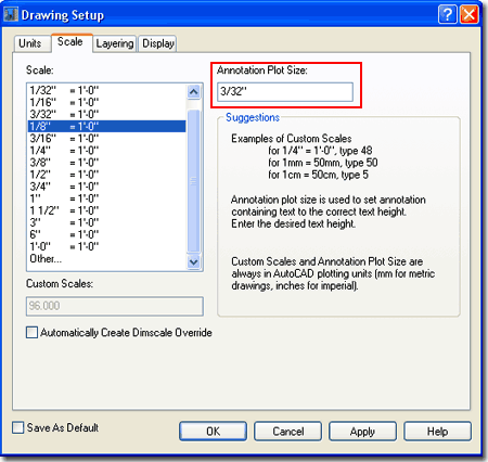
| Setting the Drawing Scale for Annotation Symbols From the Documentation pull-down menu, select Set Drawing Scale... and once on the Drawing Setup dialogue box, make sure you are on the Scale tab - as illustrated to the right. Set your preferred Drawing Scale or go to Other... at the bottom and create your own ratio. If you are new to the scale concept in AutoCAD, this is really just a way of telling the program what scale you plan to print at. This number is then used to multiply against symbols, text and dimensions so they print correctly for your specific scale. In other words, a scale of 1/4" = 1''-0" equates to a ratio of 1:48. The number 48 is now multiplied against a dimension arrow, for example, that is set to be 1/8" long when printed; but, on the screen it will measure out as ( 48 x 1/8" ) 6". It has become almost a defacto standard in CAD to use 1/8" for Annotation Plot Size but if you think in terms of Points, 10pts = 1/12 inch. This equates to 15.875mm for the Metric people but I would use 15mm myself since I've always liked text a bit smaller than 1/8". In both cases, offices standards really determine what you need to use so make sure to check existing plans. |
 |
||||||||||
Design
Content pull-down menu - Swap imperial-metric
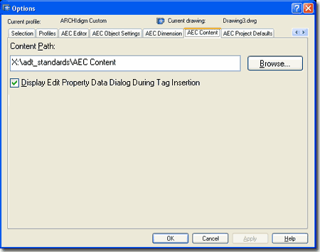
Illustrated to the right is the Options ( type "OP" ) dialogue box with the AEC Content tab active. If you work in a mixed environment that does work in imperial and metric units, this is where you can change the Content Menu to match the Design Contents - Metric or Design Contents - Imperial toolbar. If you use the toolbars, it doesn't matter what you set the Content Menu to here. Unfortunately there is no option for switching to the CSI Masterformat here but if you want it, you can use the installation CD to add it. Content Path - this is where you can set your ADT to see a common folder on an office's network server. By keeping all of the Content in one place, it's growth and change can be managed much better ( just like a block library ). Once changed, the icons will automatically look for this Path. A savvy CAD manager could set up two profiles and paths here that could switch between the Imperial default design content menu and the CSI Masterformat, but that's a bit of work. Display Edit Schedule Data Dialog During Tag Insertion - this is one of those options that you wind up living with though you can turn it off so easily. Unchecking this option is much like making Attributes Preset upon insertion. To see what this thing does, try attaching a Window or Door tag to a Window or Door and look for the Edit Schedule Data dialogue box. Uncheck this and repeat the exercise. Then, decide which option is better. Unchecked, right? I leave it unchecked. |
 |
||||||||||
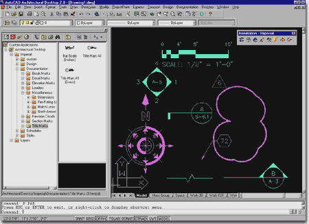
| Documentation Symbols and the DesignCenter After you have set the Drawing Scale, adding annotation symbols is a simple matter of dragging symbols from the DesignCenter Documentation folders into your drawing. Many of the symbols cary custom command sequences and unique options that require on screen picking and/or keyboard input so pay close attention to the command line. Since I am going to lobotomize the Interior Elevation Bubble in the next Section, let's look at what options you have with that symbol as you drag it in. Command: _AecAnnoElevationMarkAdd The blue input in the command sequence above is what comes automatically when you drag in an interior elevation symbol. The red input is what I did to override the default symbol settings to make an interior elevation symbol with only one filled in arrow (as illustrated to the left). With the "ATE" command (Edit Attributes), you can change the numbers to a single number. |
 |
||||||||||
| 2Adding Documentation Content | 2-17 DOCUMENTATION | ||||||||||
Adding Break Marks
|
|||||||||||
Adding
Detail Marks
Illustrated to the right, I show a couple of typical examples and one example that demonstrates some of the options available on the command line while inserting one of these Detail Marks. When drawing a cut-through Detail Mark, you first create the line and then you can use the Break option to create a break in this line. If you choose the break, you can continue drawing the line until you hit enter. Once you have ended the Detail Mark line, a Detail Bubble will automatically be inserted. You will be queried for the information to be placed in the Detail Mark and the final step will be to point in the direction you want the cut-direction arrow. Object Types: |
 |
||||||||||
Adding
Elevation Marks
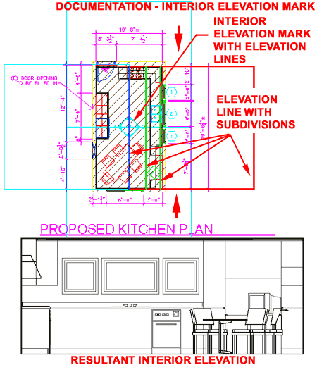
When you drag-n-drop an interior elevation mark into your drawing, depending upon which symbol you use, there are command line options that need to be answered. With the common four point symbol illustrated to the right, you will be asked which direction will represent 1 or North, what Sheet number you want for the bubble and if you want Elevation Lines. If you plan on using your Elevation Mark to generate Elevations, then you would most likely choose to have the Elevation Line included ( note this is not the default setting ). Illustrated to the right, I show how you can apply the lessons learned in the discussion about Elevations to an Interior Elevation. By adding Subdivisions and adjusting the 2D Section/Elevation Style Display Props, you can make the cutting edge bold and create a series of lighter lines for objects within the Interior Elevation. My example and this tool may not be perfect, but a lot of work can be done before you go for the manual task of finishing off your interior elevations. Object Types: Note: |
 |
||||||||||
Adding
Leaders
The Leaders folder offers |
|||||||||||
Adding
Miscellaneous
The Dimensions folder offers the same dimensions that you can find on the Dimension's toolbar but these are set to a pre-defined AEC type Dimension Style and they automatically key to a specific layer ( A-Anno-Dims if you use the AIA format ). These seem to conflict with the AEC Dimension objects found on the Documentation pull-down menu, so you may choose to ignor these. If nothing else, they demonstrate how ordinary AutoCAD tasks can be make a bit smarter with ADT tools. The Fire Rating Lines folder offers linetypes for various hour ratings on Walls and require you to select an existing ADT Wall in order to work. You may find that creating Wall Styles with linetypes in them works better. The Match Lines folder offers a couple of match line options based on a Pline and Text. The North Arrows folder can probably be considered the most useful folder in the group ( if not the only useful one here ). |
|||||||||||
Adding
Revision Clouds
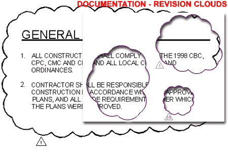
To draw a Revision Cloud, you will need to draw in the counter-clockwise fashion and then conclude the routine by coming back to the original arc segment. The cloud will automatically terminate and if you have a Tag to insert, you will be queried for its location and number. |
 |
||||||||||
Adding
Section Marks
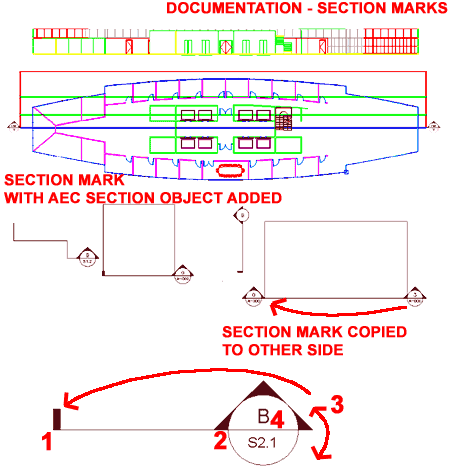
Illustrated to the right, I show that you can use the Section Mark for both annotation and automatic Section Generation with subdivision lines and everything. When you add a Section Mark you should find the option to Add AEC section object? [Yes/No] <N>: Adding this object will provide the means to Generate a Section. See the discussion on Sections for more information on how to accomplish this.
|
 |
||||||||||
Adding
Title Marks
The Title Marks folder offers |
|||||||||||
Adding Elevation Labels
The Elevation Labels folder offers |
|||||||||||
Adding
Chases
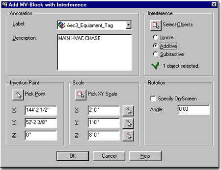
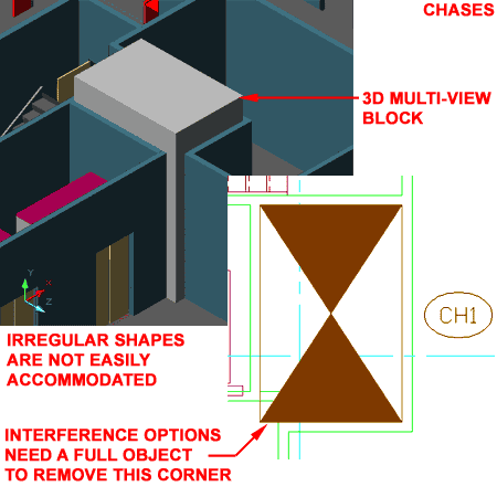
In my opinion these objects are not worth your time. First, they do not accomodate irregular shapes unless you do extensive Interference work and second, it's far to easy to create one that produces error messages on the Dimensions tab of the Modify Multi-View Block dialogue box ( just try to draw one from an upper right corner down to a lower left corner and then try to Modify it). Label - in order to used this option, you must have a label object defined in your drawing. Just having Property Definition Set Style loaded isn't enough, you will need to have one of the tag symbols in the drawing for the Label drop-down list to see it. All this does, is automatically activate the insertion of the label or tag at the end of the Chase creation process, so this is not critical; in other words, you can just insert the tag later. Object Types: |
 |
||||||||||
| Adding
Chases Example Description - this is the same Description field that you get on the Multi-View Block Properties dialogue box and is also not critical. The nice thing about a Description though, is that it will be easier for another person to know what you had in mind for this Chase when you created it. Interference - this is an option similar to the Mass Elements or Interference options with other objects. By using and interference, you can make a Chase punch out ( Subtractive) a hole right through other selected ADT objects; like Walls, Slabs and Spaces. Another option is to make your Interference Additive so that your Chase is modified to match surrounding Walls and Columns; in other words, you use this whenever your Chase is not perfectly rectangular. Insertion Point - is simply where you want one corner of the Chase to start. Scale - is simply where you want to other corner of your Chase to end. Notice that there is a Z-axis value to define how tall your Chase should be and this is important if you plan to use it as an Additive or Subtractive Interference condition. It is also important if you want to display your Chase correctly in a 3D view. Rotation - this is the same as orther rotation options in AutoCAD and ADT and refers to the Plan View rotation, not the Vertical rotation. |
 |
||||||||||
| 3Modifying Documentation Content | 3-17 DOCUMENTATION | ||||||||||
| A word about the nature
and quality of ADT's Design Content The first thing to be stated about the Design Content objects is that they vary in structure, complexity and object type. Some are simple Plines while other are nested Blocks wrapped inside a Multi-View Block ( with Attributes and everything ). This makes the discussion of Modifying them almost as lengthy as discussing each and every symbol. Instead, I'll categorize the main types. The second thing to be stated about the Design Content objects is that many of them are just plain lousy haphazard objects that appear to have been created by amateurs. If you inspect the Break Mark symbols, for example, you will discover redundant hatch patterns and poorly designed Cut Line objects that have to be Stretched in very careful ways to avoid bad results that would never happen if you just drew your own Cut Line objects. |
Simple objects - cut lines. Simple objects in complex structure - detail symbols. Multi-View Blocks Dimensions |
||||||||||
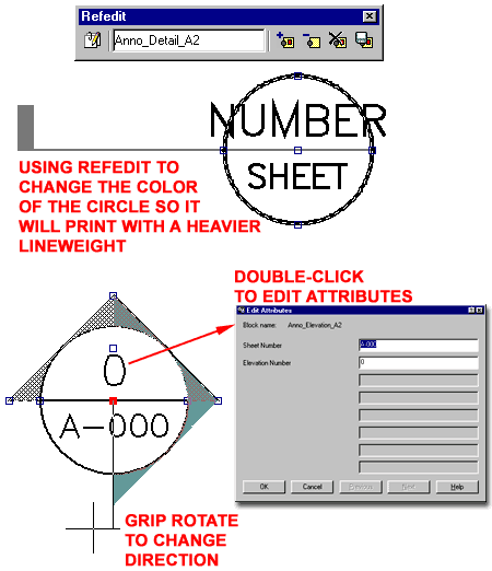
| Documentation - Block and Attribute Editing Most of the Documentation objects use Blocks with Attributes. This means that you can use common AutoCAD commands to work with these symbols; commands like AttEdit, RefEdit, Insert and Explode. To edit the text within Documentation objects, you should find that double-clicking on the symbols or text will activate the Edit Attributes dialogue box. If this does not work, try using the "AttEdit" or "ATE" commands. To edit the symbol or attribute within a Documentation object, you should find that the RefEdit command will allow you to go inside and change or add linework or text to these symbols. Since these symbols are blocks, you can also Insert them at a one-to-one ration ( scale of 1 ), explode them, edit them and re-Block them with the same name. Inserting Documentation objects from the Insert Block dialogue box will not produce the same results as with the drag-n-drop technique from the DesignCenter. This is because the DesignCenter triggers a sequence of commands while insert simply brings in a block. |
 |
||||||||||
| Documentation - Text Style and Fonts
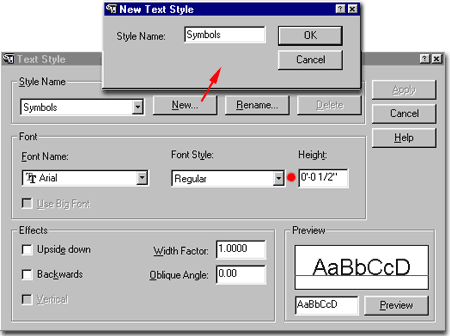
You can change the Font for this Style if you have already used it for your Documentation Symbols or you can create a New Text Style, as illustrated to the right. The Height of the Text Style is not important because it is determined by the Annotation Plot Size. |
 |
||||||||||
| 4Modifying Documentation Symbols to Create your Own | 4-17 DOCUMENTATION | ||||||||||
| Symbol
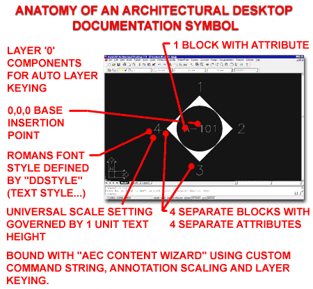
Anatomy If you have read about the Annotation Symbols ( Fixtures, Symbols and Multi-View blocks) then you might expect the Documentation Symbols to be just like the Annotation Symbols but they are quite different. Most, if not all, of the Documentation Symbols activate a command sequence when they are dragged in to a drawing, as illustrated in the comments directly above. This means that if you want to modify their behavior it isn't just a matter of re-defining a block or Multi-View Block. And if you want to design your own Documentation Symbols, you will certainly want them to be as "intelligent" as those that come with ADT. The Interior Elevation Mark, illustrated to the right, not only has a command sequence but has its own command: _AecAnnoElevationMarkAdd. You can test this command by typing "AnnoElevationMarkAdd". Within this command are various options that allow for custom settings ( [Symbol/Arrow/Type] ). Basically, it's an expanded insert command with special options related to interior elevations. Since I am accustomed to using Interior Elevation Symbols that have the Symbol Number or Letter on top and the Sheet Number on the bottom, I thought changing this symbol might be a good exercise. What follows is thus more of an exercise than an explanation of organization. |
 |
||||||||||
| Editing
Existing Documentation Symbol
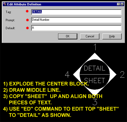
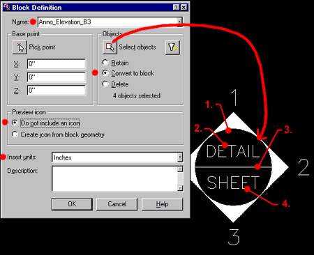
1) Explode the center block by picking on the word "sheet". 2) Draw a horizontal Line from quadrant to quadrant, as illustrated to the right. 3) Copy the word "sheet" up or down and use the Move command to align the two "sheet" words. 4) Use the Edit Text command ( "ED" ) to modify the Attribute Definition. Tag: DETAIL
|
 |
||||||||||
| After making
the changes described above, you will need to Block the center piece that we Exploded
earlier. 5) Use the Block command ( "B" ) and use a name very close to the original center piece name. the original center piece block name was "Anno_Elevation_B1". I show, in the illustration to the right, "Anno_Elevation_B3" as the new name because Architectural Desktop already has a symbol that uses a block named "Anno_Elevation_B2" and we don't want block re-definitinions. 6) For Base point you should not have to specify anything since the original symbol was centered on 0,0,0. But, if you are working on other symbols, changing symbol behavior or building one from scratch, you will want to make sure that the Base point is at the center or other specific point on the symbol. 7) For Objects, make sure you select the right objects (not too many and not too few). The tricky one, in this example, is the circle around the text. Pick the two pieces of text in the order that you want them to show up in the Attribute Dialogue box when you use this symbol. To make life easier, check the Convert to block option so you won't have to insert this symbol when done. 8) For Preview Icon, I choose not to include something that only eats up extra memory. 9) For Insert Units, use what you are working in. |
 |
||||||||||
| Once you have
the modified block completed, as outlined above, you will need to activate the AEC
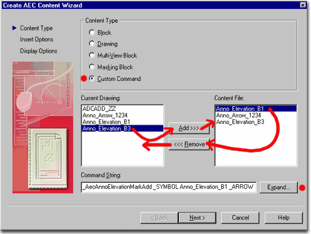
Content Wizard from the Desktop pull-down menu. On the Create AEC Content Wizard dialogue box, check the Custom Command radio button and notice that you already have information in the Content File list. This is because we are currently in a file that has been built this way. 10) Since we want our own center piece used as a block within our custom Interior Elevation Mark symbol, we need to <<<Remove the current "Anno_Elevation_B1" block and Add>>> our own "Anno_Elevation_B3" block. 11) For Command String, the part that makes these symbols so "intelligent", pick on the Expand... button and go to the next step below. |
 |
||||||||||
| On the Custom
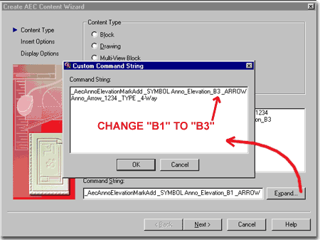
Command String dialogue box, change the name of the existing center piece block
to the name of the one we created earlier: "Anno_Elevation_B3".
See, all we really have to do is change a "1" to a "3" - life can be
easy with some planning. Ok Next> |
 |
||||||||||
| 12) On the Insert
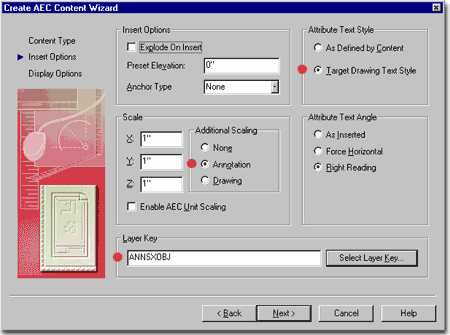
Options part of the Create AEC Content Wizard dialogue box, you
should find an amazing assortment of options for how you want to control the behavior of
your custom symbol. For this example, the modified Interior Elevation Mark, we don't
need to change anything because it has all been set for the original
symbol. Now you could make changes if you feel it is needed. Perhaps you don't
like the layer the default ADT symbols are keyed to. Next > Note: Among the many cool options you have on this dialogue box, notice the Attribute Text Style option - setting this to Target Drawing Text Style allows you to define the Font of a symbol in the file that the symbol is inserted into; i.e., the text becomes what the current style is in the target drawing. The other option, Additional Scaling, is set to "Annotation" (see graphic above). This means that the size of the Drawing Text, as defined in the Text field on the Scale tab of the Drawing Setup dialogue box, defines the size of this symbol; i.e, the symbol is controlled by the text height setting. |
 |
||||||||||
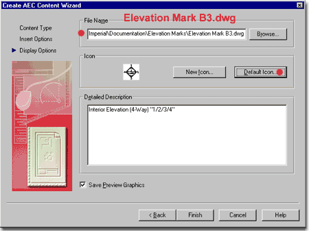
| 13) On
the Display Options part of the Create AEC Content Wizard
dialogue box, you will need to specify a File Name and Folder
for your new Interior Elevation Mark symbol. Since we want this new symbol to join
those already organized for the DesignCenter, we need to place it in the exact same folder
with the other Elevation Marks. And just to make the naming convention similar, I
show that I am naming my new symbol: "Elevation Mark B3.dwg". 14) For Icon, pick on the Default Icon... button to get an updated image showing your changes. One small problem with this is that you may end up with a black background and white lines because of how your background color is set in ADT. 15) You can add any description information you want and then make sure the Save Preview Graphics check box is checked. Finish Now Exit or Close the current drawing and make sure not to save any changes. We don't want to ruin the default ADT symbol. Open a new drawing and test your symbol. If it has problems, you can now open it and work on it. If you need to run it through the AEC Content Wizard again, you will have to save it with another temporary name first because the AEC Content Wizard won't allow you to output over a file that is currently open. |
 |
||||||||||
| 5Documentation - Customizing and Tricks | 5-17 DOCUMENTATION | ||||||||||
© Copyright 2001- 2004 ARCHIdigm. All rights reserved.