Columns:Hardcore Game Programming
Graphics:Cg
| Cg Bumpmapping | |
| See Also: Columns:Hardcore Game Programming Graphics:Cg |
Cg Bumpmapping
Get the demo, source, and documentation for this article here.
This article describes how to implement a simple and effective bump mapping effect using nVIDIA's Cg programming language and OpenGL.
Although the focus of the article is on Cg, a limited amount of bump mapping theory is necessary and will be presented first. Additional bump mapping references are listed at the end of the article.
The goal of bump mapping is to create the illusion of "ridges" and "valleys" on otherwise flat surfaces. Here is an example [1]:
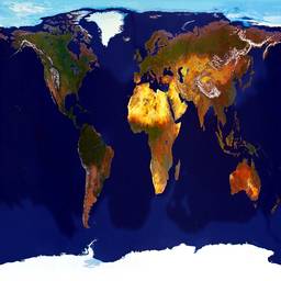 Flat surface |
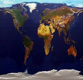 Bump mapped surface |
The color of a surface is determined by the angle (dot product) between the normal vector of that surface and the light vector:
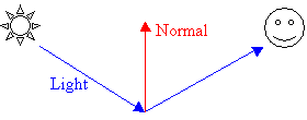
The light source is assumed to be placed "at infinity", and all rays from it are parallel to each other by the time they reach the surface.
On a flat surface, the normal vector is the same everywhere on that surface, so the color of that surface will be the same everywhere.
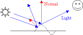
If the normal vector could be perturbed at various points on that surface, it would yield areas that are darker or lighter, thereby creating the illusion that parts of the surface are raised or lowered:
In order to compute the normal vector at every point on the surface, we need some additional information about whether points on that surface are "high" or "low". We use a height map to store this information (dark areas are "low", light areas are "high") [1]:
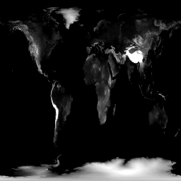
The normal vector at a point is defined as the cross product of two tangent vectors to the surface at that point. The points in the height map range from (0,0) to (width, height) in a two-dimensional system of coordinates:
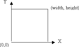
We define two tangent vectors to the surface at (x, y) as follows (heightmap[x, y] represents the height at (x, y)):
t = (1, 0, heightmap[x+1, y] -
heightmap[x-1, y])
β = (0, 1, heightmap[x, y+1] - heightmap[x, y-1])
The normal vector η at (x, y) is the normalized cross product of t and β. If (x, y) is a point in an area of the height map where the neighborhood is all the same color (all black or all white, i.e. all "low" or all "high"), then t is (1,0,0) and β is (0,1,0). This makes sense: if the neighborhood is "flat", then the tangent vectors are the X and Y axes and η points straight "up" along the Z axis (0,0,1). If (x, y) is a point in an area of the height map at the edge between a black and a white region, then the Z component of t and β will be non-zero, so η will be perturbed away from the Z axis.
Note that η has been computed relative to the surface that we wish to bump map. If the surface would be rotated or translated, η would not change. This implies that we cannot immediately use η in the lighting equation: the light vector is not defined relative to the surface but relative to all surfaces in our scene.
For every surface (triangle) in our scene there are two frames of reference. One frame of reference, called texture space (blue in the figure below), is used for defining the triangle texture coordinates, the η vector, etc. Another frame of reference, called object space (red in the figure below), is used for defining all other triangles in our scene, the light vector, the eye position, etc.:
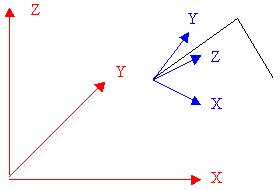
In order to compute the lighting equation, we wish to use the light vector (object space) and the η vector (texture space). This suggests that we must transform the light vector from object space into texture space.
Let object space use the basis [(1,0,0), (0,1,0), (0,0,1)] and let texture space use the basis [T, B, N] where N is the cross product of the two basis vectors T and B and all basis vectors are normalized. We want to compute T and B in order to fully define texture space.
Consider the following triangle whose vertices (V1, V2, V3) are defined in object space and whose texture coordinates (C1, C2, C3) are defined texture space [2]:
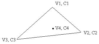
Let V4 be some point (in object space) that lies inside the triangle and let C4 be its corresponding texture coordinate (in texture space). The vector (C4 - C1), in texture space, can be decomposed along T and B: let the T component be (C4 - C1)T and let the B component be (C4 - C1)B.
The vector (V4 - V1) is the sum of the T and B components of (C4 - C1):
V4 - V1 = (C4 - C1)T * T + (C4 - C1)B * B
It follows immediately that:
V2 - V1 = (C2 - C1)T * T + (C2 -
C1)B * B
V3 - V1 = (C3 - C1)T * T + (C3 -
C1)B * B
This is a system of two equations with two unknowns (T and B) that can be readily solved for T and B:

where
t1 = (C2 - C1)T, t2 = (C3 -
C1)T
b1 = (C2 - C1)B, b2 = (C3 - C1)B
By definition, the matrix that transforms vectors from texture space to object space has as columns the vectors T, B, N. The inverse of this matrix transforms from object space to texture space. For example, this (inverse) matrix will take the triangle normal (from object space) and map it to the Z axis (in texture space); similarly, this (inverse) matrix will take the light vector (from object space) and transform it to texture space. At this point, we can use η and the newly transformed light vector to compute the lighting value at every point in the height map.
"Cg is a language for programming GPUs. Cg programs look a lot like C programs." [4]
The GPU stands for Graphics Processing Unit: it is a specialized integrated circuit that can perform complex graphics computations. The two GPU operations that can be programmed via Cg are: vertex operations and fragment operations.
A Cg vertex program can perform certain computations on the GPU for every vertex defined in a mesh. A Cg fragment program can perform certain computations on the GPU for every fragment (pixel or point on the screen) in a mesh. Cg provides a number of graphics-specific primitives (such as vector dot- and cross- products, matrix multiplications, etc.)
Any Cg program expects certain parameters as input and is required to produce certain parameters as output. For example, a Cg vertex program probably needs the position of the current vertex and some matrix as input and is required to produce the modified position of the current vertex as output. Similarly, a Cg fragment program probably needs the position of the current fragment and some color and/or texture parameters as input and is required to produce the color of the current fragment as output.
The parameters for a Cg program are of two types: varying and uniform. Varying parameters, as the name implies, vary for every graphics element drawn on the screen (for example, the vertex position is a varying parameter to a vertex program). Uniform parameters are the same for the current batch of graphics elements (for example, the ambient light color is a uniform parameter to a fragment program).
The vertex program always runs before the fragment program, and the output from the former can be fed directly into the latter.
Cg programs are "compiled" into "assembly" code that is specific to the targeted GPU and the associated software driver. For example, a vertex program written in Cg can be compiled and targeted to the DirectX profile or to the nVIDIA (proprietary) OpenGL extensions. The Cg runtime can be instructed to silently select the most appropriate compiler target for the current platform.
A (syntactically and semantically) valid Cg program may fail to compile due to hardware limitations. For example, the program may require more registers (or combiner stages) than are available on the GPU. In this case, you would need to modify the program, remove features from it, or buy better hardware.
For further information about the Cg language and supporting API, refer to the official nVIDIA documentation [3].
Before using any of Cg's facilities, you need to perform a few global initialization steps.
The Cg API returns error codes after each operation. You can either test these error codes explicitly, or you can setup a global error callback function that is called whenever an error is encountered. For simplicity, we prefer the error callback approach:
void cgErrorCallback()
{
    CGerror err = cgGetError();

    if (err != CG_NO_ERROR) {
        cerr << "cgErrorCallback(): " << cgGetErrorString(err) << endl;
        exit(1);
    }
}
To instruct Cg to use this error callback, call this API:
cgSetErrorCallback(cgErrorCallback);
All Cg programs (and their data) are stored in a global Cg context (one per application/process):
In order to compile and load a Cg program, you need to specify whether the program is a vertex or a fragment program first (select and configure the appropriate profile). If your hardware/software supports multiple versions of such profiles, it is a good idea to select the latest (most advanced) one (as a way to "future-proof" your code and make sure that, as hardware evolves, it will continue to work):CGcontext context = cgCreateContext();
CGprofile profile = cgGLGetLatestProfile(CG_GL_FRAGMENT);
cgGLSetOptimalOptions(profile);
The API "cgGLSetOptimalOptions" will setup the optimal compilation parameters for the selected profile. We are now ready to compile and load our Cg program (from "[file name]"):
CGprogram program = cgCreateProgramFromFile(
    context,
    CG_SOURCE,
    [file name],
    profile,
    NULL,    // entry point
    NULL);   // arguments

cgGLLoadProgram(program);
If the entry point is not specified, it defaults to "main" (the vertex or fragment program begins processing at the function "main"). The arguments parameter is an array of arguments passed directly to the compiler.
Once the Cg program has been compiled and loaded, it must be bound and enabled. The binding step is necessary since you can load multiple Cg programs in an application, but you can only use one as the current vertex or fragment program.
cgGLBindProgram(program);
cgGLEnableProfile(profile);
At this point, the Cg runtime has been properly setup and initialized and your Cg program is ready to receive input parameters, run and produce output.
See end of the article for a complete code listing of the code snippets described above.
We are now ready to implement the bump-mapping algorithm described above in Cg.
Let's collect and summarize all the parameters that are necessary for performing the bump mapping calculation for every pixel (fragment) of our mesh:
We first add (1, 1, 1) to η in order to bring its components between [0, 2]. We then divide it by 2, to bring its components between [0, 1]. Lastly, we multiply it by 255, to bring its components between [0, 255]-suitable for storage in a texture. This is a uniform parameter.η = ((η + (1, 1, 1)) / 2) * 255
Here is what the Cg code looks like:
float4 main(float2 detailCoords : TEXCOORD0,
            float2 bumpCoords: TEXCOORD1,
            float3 lightVector : COLOR0,
            uniform float3 ambientColor,
            uniform sampler2D detailTexture : TEXUNIT0,
            uniform sampler2D bumpTexture : TEXUNIT1): COLOR
{
    float3 detailColor = tex2D(detailTexture, detailCoords).rgb;

    // Uncompress vectors ([0, 1] -> [-1, 1])
    float3 lightVectorFinal = 2.0 * (lightVector.rgb - 0.5);
    float3 bumpNormalVectorFinal = 2.0 * (tex2D(bumpTexture, bumpCoords).rgb - 0.5);

    // Compute diffuse factor
    float diffuse = dot(bumpNormalVectorFinal, lightVectorFinal);

    return float4(diffuse * detailColor + ambientColor, 1.0);
}
Let's look first at the program declaration and parameters.
The program consists of a single function, called "main"; this is the entry point into the program. The function is declared to return a "float4" (a vector consisting of 4 floating point values: this is the required output color from the fragment program). The function receives a number of parameters as input: some are tagged "uniform" (these are the uniform parameters) and some are not (these are the varying parameters).
Some parameters are followed by a colon a keyword (for example, "float2 detailCoords : TEXCOORD0"). The colon indicates a binding semantic and the keyword is the target of that binding. For example, ": TEXCOORD0" indicates that the parameter to the left of it will receive the values of the texture coordinates for the current vertex from the first texture unit. Here is a listing of all binding semantics used in this program and their meaning:
| Binding Semantic | Meaning |
| TEXCOORD0 | The texture coordinates in the first texture unit for the current
vertex: glMultiTexCoord2fARB(GL_TEXTURE0_ARB,x, y); |
| TEXCOORD1 | The texture coordinates in the second texture unit for the current
vertex: glMultiTexCoord2fARB(GL_TEXTURE1_ARB,x, y); |
| TEXUNIT0 | The texture bound to the first texture unit: glActiveTextureARB(GL_TEXTURE0_ARB); glBindTexture(GL_TEXTURE_2D,handle); |
| TEXUNIT1 | The texture bound to the second texture unit: glActiveTextureARB(GL_TEXTURE1_ARB); glBindTexture(GL_TEXTURE_2D,handle); |
| COLOR0 | The color for the current vertex: glColor3f(r,g,b); |
| COLOR | The color (output) from the fragment program. |
Note that one parameter in the Cg program above does not have a binding semantic (the "ambientColor" parameter). This uniform parameter will be set using the Cg API. First, we retrieve the symbolic parameter from the Cg program:
CGparameter ambientColorParameter = cgGetNamedParameter(program, "ambientColor");
Then we set its value:
cgGLSetParameter3f(ambientColorParameter, r, g, b);
Let's look now at the program implementation.
The first line retrieves the color from the detail texture and stores it into a vector:
float3 detailColor = tex2D(detailTexture, detailCoords).rgb;
Note the ".rgb" ending of the line: this is called a swizzle. Although every element in the texture consists of 4 floating-point values (red, green, blue, and alpha), we are only interested in the color components. The ".rgb" ending retrieves only the first 3 floating-point values, suitable for storage in a "float3" vector. You can re-order or duplicate the entries in the swizzle as you wish, for example: ".bgr", ".rrr", ".rrg" etc.
The following two lines perform the inverse of the range compress operation described above in order to retrieve the signed representation of the light and η vectors (note, again, the use of the swizzle operator):
float3 lightVectorFinal = 2.0 * (lightVector.rgb - 0.5);
float3 bumpNormalVectorFinal = 2.0 * (tex2D(bumpTexture, bumpCoords).rgb - 0.5);
We are now ready to compute the lighting value as the dot product between the light vector and η (we use the built-in Cg "dot" function)
float diffuse = dot(bumpNormalVectorFinal, lightVectorFinal);
Finally, we compute the output color as a combination between the detail texture color and the ambient color:
return float4(diffuse * detailColor + ambientColor, 1.0);
Since we return a vector consisting of 4 elements, we fill in the last one (the alpha value) with 1.0.
Software Environment
The code that accompanies the article has
been compiled and tested only on Microsoft Windows 2000 Professional SP3 and
Microsoft Visual Studio .NET (version 7.0). The code includes the necessary
Visual Studio project files and configuration.
You will need the following 3rd party libraries:
Hardware Environment
The code has been tested on a GeForce4 Ti
4200 video card. The code should run on a GeForce3 (or better) or a Radeon 9500
(or better) card.
In general, Cg OpenGL requires a GPU with support for either ARB_vertex_program/ARB_fragment_program (GeForceFX (or better) or Radeon 9500 (or better) families) or NV_vertex_program/NV_texture_shader/NV_register_combiners (GeForce3 (or better) family).
To execute the pre-compiled binaries, you need to use the following command line:
C:\>Bumpmap.exe Cube.ms3d Fragment.cg
The first parameter specifies the 3D Model to render on the screen, and the second parameter specifies the Cg fragment program to use in order to render the faces of the model.
Once the application window appears on the screen, you can right-click anywhere in it and display a pop-up menu with four options in it:
The code that accompanies this article (and implements the concepts described within) has a few additional features that go beyond the scope of the article.
In particular, the Cg code computes both the diffuse and the specular component for the lighting model, for which reason it is longer and slightly more complicated.
The triangle mesh rendered on the screen is a cube created using Milkshape 3D [8].
The code is documented and automated documentation is produced using Doxygen [9].
#include <Cg/cg.h>
#include <Cg/cgGL.h>

void cgErrorCallback()
{
    CGerror err = cgGetError();

    if (err != CG_NO_ERROR) {
        cerr << "cgErrorCallback(): " << cgGetErrorString(err) << endl;
        exit(1);
    }
}

void main(int argc, char* argv[]) {
    cgSetErrorCallback(cgErrorCallback);

    CGcontext context = cgCreateContext();

    CGprofile profile = cgGLGetLatestProfile(CG_GL_FRAGMENT);
    cgGLSetOptimalOptions(profile);

    CGprogram program = cgCreateProgramFromFile(
        context,
        CG_SOURCE,
        [file name],
        profile,
        NULL,    // entry point
        NULL);   // arguments

    cgGLLoadProgram(program);

    cgGLBindProgram(program);
    cgGLEnableProfile(profile);
}
#include <Cg/cg.h>
#include <Cg/cgGL.h>

void draw() {
    // OpenGL lighting must be disabled since the pixel shader
    // program will compute the lighting value
    glDisable(GL_LIGHTING);

    // The first texture unit contains the detail texture
    glActiveTextureARB(GL_TEXTURE0_ARB);
    glEnable(GL_TEXTURE_2D);
    glBindTexture(GL_TEXTURE_2D, [detail texture handle]);

    // The second texture unit contains the normalmap texture
    glActiveTextureARB(GL_TEXTURE1_ARB);
    glEnable(GL_TEXTURE_2D);
    glBindTexture(GL_TEXTURE_2D, [normalmap texture handle]);

    // Set the (fixed) ambient color value
    CGparameter ambientColorParameter = cgGetNamedParameter(program, "ambientColor");
    cgGLSetParameter3f(ambientColorParameter, [ambientr], [ambientg], [ambientb]);

    for every vertex in the triangle {
        // Bind the light vector to COLOR0 and interpolate
        // it across the edge
        glColor3f([lightx], [lighty], [lightz]);

        // Bind the texture coordinates to TEXTURE0 and
        // interpolate them across the edge
        glMultiTexCoord2fARB(GL_TEXTURE0_ARB,
            [texturex], [texturey]);

        // Bind the normalmap coordinates to TEXTURE1 and
        // interpolate them across the edge
        glMultiTexCoord2fARB(GL_TEXTURE1_ARB,
            [texturex], [texturey]);

        // Specify the vertex coordinates
        glVertex3fv([vertexx], [vertexy], [vertexz]);
     }
}
float4 main(float2 detailCoords : TEXCOORD0,
            float2 bumpCoords: TEXCOORD1,
            float3 lightVector : COLOR0,
            uniform float3 ambientColor,
            uniform sampler2D detailTexture : TEXUNIT0,
            uniform sampler2D bumpTexture : TEXUNIT1): COLOR
{
    float3 detailColor = tex2D(detailTexture, detailCoords).rgb;

    // Uncompress vectors ([0, 1] -> [-1, 1])
    float3 lightVectorFinal = 2.0 * (lightVector.rgb - 0.5);
    float3 bumpNormalVectorFinal = 2.0 * (tex2D(bumpTexture, bumpCoords).rgb - 0.5);

    // Compute diffuse factor
    float diffuse = dot(bumpNormalVectorFinal, lightVectorFinal);

    return float4(diffuse * detailColor + ambientColor, 1.0);
}
[1] nVIDIA "OpenGL SDK"
[2] Eric Lengyel "Mathematics
for 3D Game Programming & Computer Graphics"
[3]
nVIDIA "Cg"
[4] Mark Kilgard "Cg in Two Pages"
[5] Nate Robbins Windows port of Mark Kilgardís "OpenGL Utility Toolkit"
(GLUT)
[6] Chad Austin "Corona"
[7] NeHe
"OpenGL Tutorials", Lesson 22
[8] chUmbaLum sOft "Milkshape 3D"
[9] Dimitri van Heesch "Doxygen"
Discuss this article in the forums
Date this article was posted to GameDev.net:
4/15/2003
(Note that this date does not necessarily correspond to the
date the article was written)
© 1999-2003 Gamedev.net. All rights reserved. Terms of Use
Privacy
Policy
Comments? Questions? Feedback? Send us an
e-mail!