The idea of on-channels repeaters is not a new one. In some ways OCARs
are just an extension of the passive repeater which has been used for many
years on microwave links to allow communications when the path between
two stations is obstructed. Passive repeaters generally use large apertures,
either a planar reflector or a pair of antennas, placed relatively close
to one end of a radio link. They are positioned so as to intercept a significant
fraction of the transmitted power from the nearer transmitter. That power
is then either reflected directly (mirrorlike) or fed to a second antenna
and directed toward the distant end of the link over a path which is much
better than the direct path between the two end stations. Even though the
losses over a path through a passive repeater are greater than those in
freespace, these losses can be much less than what was possible over the
original, obstructed path. If the apertures are big and close enough to
catch significant power then communications can be maintained.
Terrestrial microwave links sometimes use this technique to allow the placement
of large and bulky antenna and electronics at ground level. The antenna
points upward towards a planar reflector located nearby. A reflector of
this type redirects the wavefronts to and from the ground mounted antenna
and is actually a passive repeater.
The reciprocity theorem says that this whole arrangement works in the reverse
direction as well.
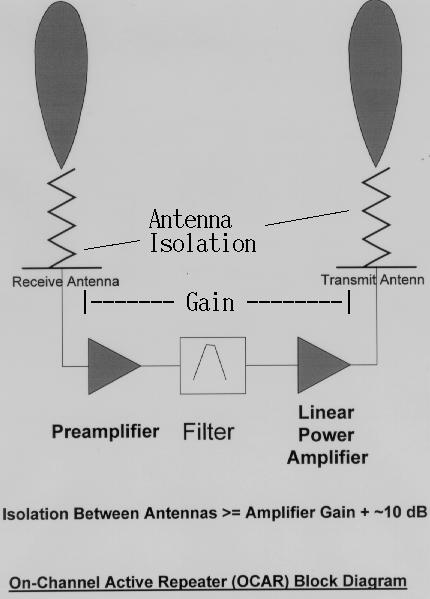
Active repeaters are an extension of this idea of "catching" power from one end of a link and redirecting it toward the other end. The active repeater does this by adding linear amplification between the "catching" antenna and the "focussing" antenna. This works as long as the isolation between the two repeater antennas is greater than the gain of the amplifier. If it is not, the system generally becomes an oscillator.
The technique has been used for one-way comunication by commerical broadcasters to fill in shadowed areas of a customer base. In many situations, the output of the amplifier needs to be no more than a few watts
Generally, the receive antenna is followed by a bandpass filter which in turn drives an output stage. The filter restricts operation to the channel or band of interest. It may be wide or narrow depending upon requirements. If very narrow filtering is required, it may be necessary to downconvert to a lower frequency where a suitable filter is more easily implemented and then re-convert back to the channel frequency. This arrangement is almost identical to the linear transponder of amateur satellites except for the lack of a frequency offset between the inbound and outbound signals. The similarity in acronyms between amateur OCARs and amateur OSCAR satellites is intentional.
For wideband modes, ATV or spread spectrum, it may be necessary to ensure that the group delay unflatness of the antennas, bandpass filter and amplifiers does not add unacceptable distortion to the signals of interest.
This idea has already been tried in the amateur world. Kerry Banke, N6IZW, has written an Update of what he and and some of the San Diego Microwave Group have been doing at 10 GHz to help encourage a base of users who wouldn't otherwise be able to communicate due to obstructed radio paths.
Here in Northern California, we have also applied it at UHF. Our first OCAR is now running on 900 MHz and we hope to add another in the 1200 MHz band soon to allow two-way communications for both digital and analog systems by "fixing" paths. See Building and Using an OCAR
OCARs have some nice attributes for amateur use:
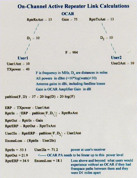
To help analyze the performance of an OCAR, here is a simple MathCad 6.0 program. Using numbers typical of our 230 kbps system, here are some sample link calculations showing how bad paths may be restored to near-freespace quality with very modest hardware.
Building and Using an OCAR
Back to What can we do? Page