Antennas may not behave as you believe they do.
- Antenna elements do not radiate.
- The actual antenna is invisible.
- Below about a half wavelength any antenna has the same SNR. A 1 cm dipole and a half-wave dipole have the same SNR on 160m!
If these assertions shock you or you are considering building up
the hybrid antenna system kit please read all the background FIRST.
This includes but is not limited to
On
the Response of an Active Dipole, Winter 22
RadCom+ (RSGB membership required)
If you are thinking of constructing this system, I strongly suggest first building the PreampA along with the Shack Board. This allows testing the construction process and also provides a tool for mapping a prospective location to verify suitably low common mode and near-field noise ingress to see if a proposed site merits committing to a traveling wave antenna and junction box as well. An Active Dipole using PreampA may suffice until other noise ingress problems are solved. There is yet another reason for building only the PreampA and the Shack board. That reason is that you may be able to completely avoid building up the PreampB and Junction to create the Hybrid antenna system and achieve the ITU curve C noise floor. If your location and siting effort indicates, it may be possible to use PreampA with a larger dipole, perhaps something on the order of 2 x 5m monopoles for a total of no more than 10m tip-tip. At this length, the antenna factor may be good enough compared to the OpAmp noise to reach ITU "quiet rural" levels all the way to 30 MHz. An antenna like this requires a vertical support that is more visible so may be a problem with HOAs and such a system is no longer "portable" for mapping but if a suitably quiet location can be determined, it may be all that is necessary to create a high quality LF through HF receive system without resorting to a Hybrid system. The visibility problem may be mitigated through hanging rather small diameter conductor from a support. With a larger dipole such as this, signal levels will also be higher which might cause an overload problem that wouldn't be present with a smaller structure. Whether or not going to a larger dipole is warranted and whether the continuation to a Hybrid system is merited will depend upon a particular site.
A QUCS-S:qucsator PreampNoise.sch
model may be used to examine possibilities. This is an
in-process modeling tool so please let me know if there are errors,
problems or if you know a better way to write this sort of model.
None of this is a "silver bullet" and there will only be
disappointment if you don't understand how to deploy this hardware.
For this system, signals and the propagated noise that you want to
become dominant at your receiving system detector are small. This
means that unwanted ingress, either from common mode currents or
near-field sources must be kept smaller still, several dB below the
hybrid systems levels. If you don't do this, your limiting noise will
not be from what you believe to be your antenna system.
Because both antennas and preamps are differential, it is easy to
verify that the intended antenna is the source of the noise. On an
installed system, if shorting the the two monopoles in front of
PreampA or the differential connections from a traveling wave antenna
connected at PreampB does not drop all signals throughout the spectrum
6-10 dB then you still have work to do! This is a test that cannot be
done on a single-ended monopole (whip) system.
Even if your installation meets this test, you may still have
near-field ingress, which is why you need to be able to calculate
absolute noise power levels and do site mapping. I suggest
building up the dipole/PreampA + Shack PCB system first and using that
to map a candidate location and polarity using a portable receiver
that can view 0-30 MHz. Polarization is important here as it affects
both take off angle and efficiency. Over typical ground going to
(H)orizontal polarization will generally incur 6-8 dB additional
attenuation at the same time the take off angle goes nearly vertical.
Don't let this fool you but consider SNR not absolute levels.
It is very helpful to use a broadband SDR or spectrum analyzer
to view the entire range in one sweep. This permits discovering
and learning about ingress that simply viewing a narrow slice of
spectrum or a single amateur band may not reveal. Propagated noise is
not 'bumpy' versus frequency. It is sometimes useful to listen to
broadband demodulated AM, perhaps in a 10 kHz or wider bandwidth, to
see if there is a noticeable mains 'hum' component that isn't obvious
in USB or narrower modes. Many local noise sources operate from
switched mode power supplies that are poorly filtered and AM detection
can reveal harmonic lines from these. Propagated noise, often produced
by lightning strikes around the world, has a different characteristic
that it is useful to learn these differences and what to listen for.
Generally, surveying an area with the dipole vertically polarized
while a few meters above the ground can help determine a potentially
good location. After an available candidate location that shows the
most promise has been found, using that as a more permanent location
is a good place to begin. If subsequent noise measurement s indicate
that it is merited, an LoE and PreampB can be installed their as
well. Count on this entire process requiring months or years!
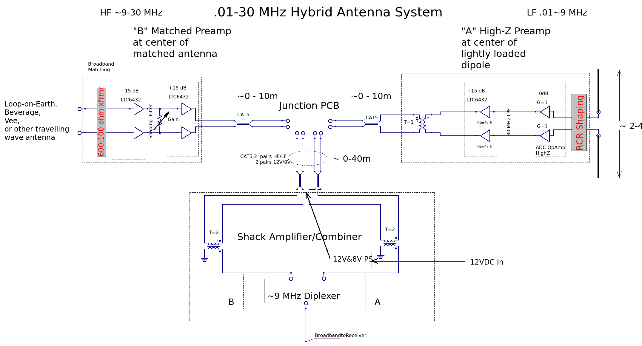
An example of the HW pieces matches the block diagram above and
looks like this picture which was taken before the same were sent off
to VY0ERC near the magnetic North Pole
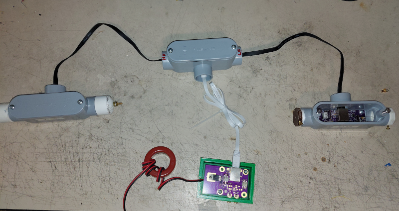
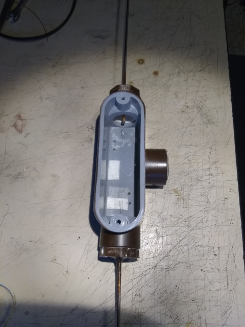
The preamps and the junction PCBs were placed inside PVC electrical
boxes which can be made waterproof. The dipole antenna connections,
the traveling wave antenna connections for PreampB are made at the
ends of the respective boxes with the CAT5 cable coming out of the "T"
arm and connecting at the ends of the Junction box/PCB. The common
CAT5 goes from the junction "T" all the way to the Shack Board.
The shack board may receive either single pair connection from the
"A" side, separate connections to a diplexer when also using the "B"
side or, in the case of the Polarimeter described elsewhere,
connections to a quadrature network for extracting O and X
polarizations from a quadripole antenna. The shack board pictured is
an earlier version.
The housing for the Active Dipole Preamp accepts two 1m long .125"
diameter stainless steel rods which are placed through PVC end caps.
Contact to them is made by wrapping .5" wide sticky copper tape around
the end of the rod and soldering a thin wire to the tape. The other
end of the wire solders to one of the antenna pads on the PreampA PCB.
The PreampB housing is similar but with connections brought out
from only one end. An intervening 5:2 turn balun is usually placed
here to convert the 100 ohm differential impedance to something near
600 ohms. For each preamp, the RJ45 connector points toward the "T"
where the CAT5 cable exits. Teflon tape can be used to ensure
hermeticity. I found it a good idea to place a thin piece of thermal
padding between the PVC bottom and the PCB to aid in extracting heat.
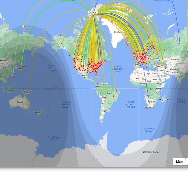
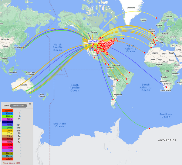
Typical 24 Hour WSPR spots from VYOERC and N6GN/K2 using a KiWiSDR
receiver and the hybrid antenna system:
