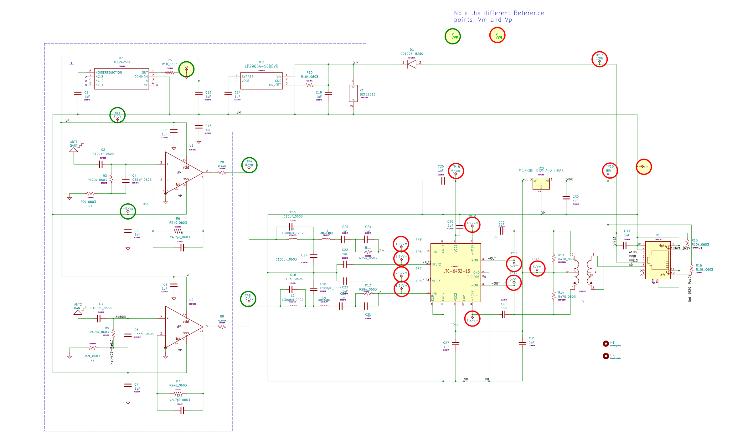
High Impedance short Dipole  pre-amplifier Board.

For better  quick  viewing of the design, download the Kit file from the Material List  below , unzip it and drop the .sch or .pcb file onto kicanvas from a web browser.

Note that the RC/R shaping at the OpAmp inputs is there to adjust shaping of the low end. In some locales, very strong LF or MF signals can cause overload of ADCs and/or IMD. This is particularly an issue when dipoles larger than 2m tip-tip are used. The parallel RC adjusts the low frequency corner while the series R to ground affects overall response but particularly at the low frequency end. This shaping is the only protection the OpAmps have from large signals.  At these high impedances filtering for other strong signals, say, 100 MHz from strong FM BCB stations, isn't possible for practical reasons.
Using QUCS simulator with a QUCSPreampANoiseModelmay be  useful in selecting different values. 

See an application in RadCom+ Winter 2022.
PreTest  PreampA

Upon receipt of the assembled Shack and Preamp PCBs from the manufacturer,  simple preliminary testing should be performed.  This should include the absence of shorts on the power supply input and the output of the 7805 LDO. THe board will already have been flying probe tested at manufacture and physically examined after all components were soldered but one more test after delivery is good insurance.

The Shack board should be tested and verified first since it can be used not only for powering the Preamps but also as an adapter to verify RF performance during testing.

Following the PreTest DC check, it is very helpful to operate two Shack boards back-to-back to use as a differential-to-coax adapter   for verifying cabling as well as the PCBs themselves and in particular the LPF and HPF.  

Use Shack board to test Preamps

Once the Shack board is verified it can be used to verify PreampA and PreamB later if it is built as well.  PreampA connected with a Shack Board has two filters, the LPF in the diplexer as well as the RCR filter at the input of the OpAmps, e.g. R3||C4 +R1,  This filtering acts to roll of the low frequency response to protect the receive system from very large LF and MF signals. The effect of this filtering can be seen by using a simple QUCS model.

Once there is confidence that everything is OK with the Shack and PreampA PCBs, 12VDC power can be applied to the Shack PCB and 8V output voltage measured and the adjustment set for 8V.   If possible it is a good idea to provide the 12VDC from a current limited bench power supply as extra insurance.  Normally PreampA current should be no more than .25A  so setting a current limit point slightly higher than this will ensure that if something has gone wrong, excessive current can't flow and damage a component. 

Assembly

As given on the material list, the preamps are easily mounted in common PVC 3/4" electrical T boxes. These accept 3/4" PVC pipe readily found in hardware stores and used for both electrical and landscape water systems.  Two holes need to be drilled to mount the Preamps. Place some thermal padding between the bottom of the PCB and the box to help remove heat from the PCB. PreampA dissipates more than 2 watts so keeping the PCB relatively cool in hot climates is important.  This technique has worked well even in climates that got quite hot in summer and cold in winter.

The PVC hardware may not be readily available outside of North America. For that situation, the user will need to find a way to accomplish the same goals; an enclosure that can keep the PCB dry, keep it adequately cool while providing connection for the antenna rods or wires. Ham ingenuity and a knowledge of suitable  locally available enclosures may be necessary for this. Identifying all possibilites world wide is well beyond the scope of these instructions.

Test

PreampA DC Testing

Using the test point locations below, verify the supply voltagesare as indicated. Notice that there are two different reference points for measurement, VMref and VPref ,when making these measurements. Points marked "SAME" should be within a few millivolts of each other.


RF testing is best done using a scalar or vector network analyzer such as the nanoVNA. These are 50 ohm unbalanced measurement devices and since the preamps have balanced inputs and outputs, a 1:2 transformer such as the Mini-Circuits T2-1 is useful to create a differential 100 ohm test environment.  As an alternative, the binocular core from a 300:75 ohm FM/TV transformer can be rewound with 3:2 turns. These measurements are not meant to be precise, only functional so the impedance error is not critical. If desired, a short, open, load calibration may be preformed  at the differential connections for improved accuracy. 

Noise testing is best done with a spectrum analyzer (SA) or broadband SDR having continuous coverage of .01 - 30 MHz.  Either a TinySA or a KiwiSDR works fine for this. Broadband sweep is important since it can identify problems that wouldn't be obvious with banded ham-band-only receivers.

Approximate gain measurement should show on the order of 10 dB gain for PreampA. PreampA should show relatively flat gain across .01-30 MHz in a 100 ohm environment where the low frequency shaping will have little effect.

Because the preamps are both fixed gain, when used with a calibrated SA or SDR both the total gain and noise relative to the antenna connections is determinate. Both have spectral shaping that will affect the measured response as well as the final response when used with the intended dipole or traveling wave antenna system.  The PreampA system can be modeled from theoretical antenna impedance.

For PreampA, modeled noise is compared to the ITU curve C noise when using a 2 m short dipole (solid)  and alwo with a 4m dipole (dashed) in the following  graph in green:
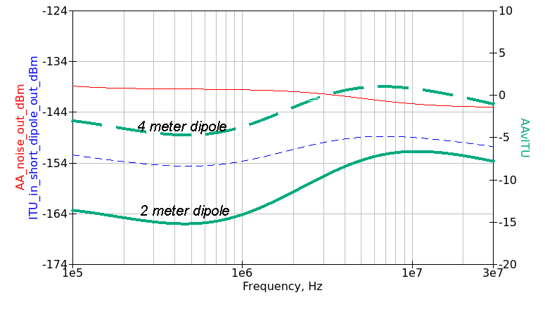
This shows that the PreampA path with 2x1m monopoles misses the ITU target by at least 6dB, partly because of mismatch from low frequency shaping and partly because of the noise present in the OpAmp's inputs.  Even so, since that target is ITU "quiet rural",  PreampA with the two 1m monopoles may still be adequate at sites that haven't achieved this level because of near-field or common mode noise.  Red and blue plots are for this 2 m dipole case.

The graph also shows that a larger dipole can produce a result that is closer to or even exceeds the ITU target in some frequency range.  However this comes with the risk of over-driving the preamp  or other down-stream stages by strong signals in the mid-HF range and possibly producing greater IMD products.  A larger dipole is also less portable and not as convenient for site mapping. This may predicate using PreampB with an LoE to achieve a better system.

From an even broader view, this sensitivity and the trade-offs highlight the ongoing nature of optimizing and localizing a receiving site.  There are multiple inter-acting factors and achieving the best results for a given situation is not only a unique but also an ongoing process.  


Material List

What you will need to build this hardware


Item Description

Provider

Source Code

Notes

Approximate Material Cost

(excludes setup fees and shipping)

Assembled PreampA PCB

Download PreampA Kit Files

Download PreampA Source Files

Investigating xfrmr change to improve LF response.
US$45

Stainless Steel Monopole, 2 required

American Radio Supply


Or similar. May be available cheaper elsewhere. US$28

Thermal Padding


Mouser


Other sources possible. Enclosure needs to accept 84mm wide PCB. US$7

Enclosure 3/4" PVC Electrical box tee

Amazon


Available in North America, substitution may be required elsewhere
US$16


 Back to HW Menu