High
Impedance Traveling-Wave Antenna Preamp
This project is for a differential input shaped-gain preamplifier.
Using a preamp with gain that increases with frequency can be
important to reach the "quiet rural" ITU propagated noise level
target. Aat the same time protecting a receiver from too-strong low
and mid frequency signals and energy is particularly necessary for
broad-band receivers such as SDRs. Shaping the gain between the
radiation resistance of an antenna, particularly a wide-bandwidth one,
may be required to avoid overloading an SDR's ADC at the low frequency
end while still maintaining enough signal and noise levels to maintain
their dominance at the ADC and detector.
This preamp is particularly useful when following a balanced
traveling wave antenna that is being operated over a significant
bandwidth rather than a lower impedance narrower bandwidth and higher
Q 'resonant' antenna. When used with an additional input transformer
to provide transformation from its 100 ohm input impedance to
perhaps 600 ohms and also act as a balun to maintain or provide
symmetry it becomes a good candidate for use with an LoE or Beverage
antenna.
The gain sloping circuit used here is described by Clint, KA7OEI,
and should be read and understood. Because in the end, every receiving
system and location is unique, understanding this makes the path to
tailoring the gain shape for a particular situation easier. The values
used in this kit may be altered at production time by simply selecting
a different JLCPCB C# when a fabricated and assembled PCB is
ordered. Of course, larger changes in the shaping circuit and
the whole design may also be accomplished by using the Hardware Source
code to create an end result even more tailored to meet one's needs.
It's also possible to remove the shaping and obtain a relatively
flat response with higher maximum gain by eliminating or bypassing
shaping components. Maintaining differential input with high
performance amplifiers can still provide low IMD and broad frequency
coverage which may be desirable for other applications.
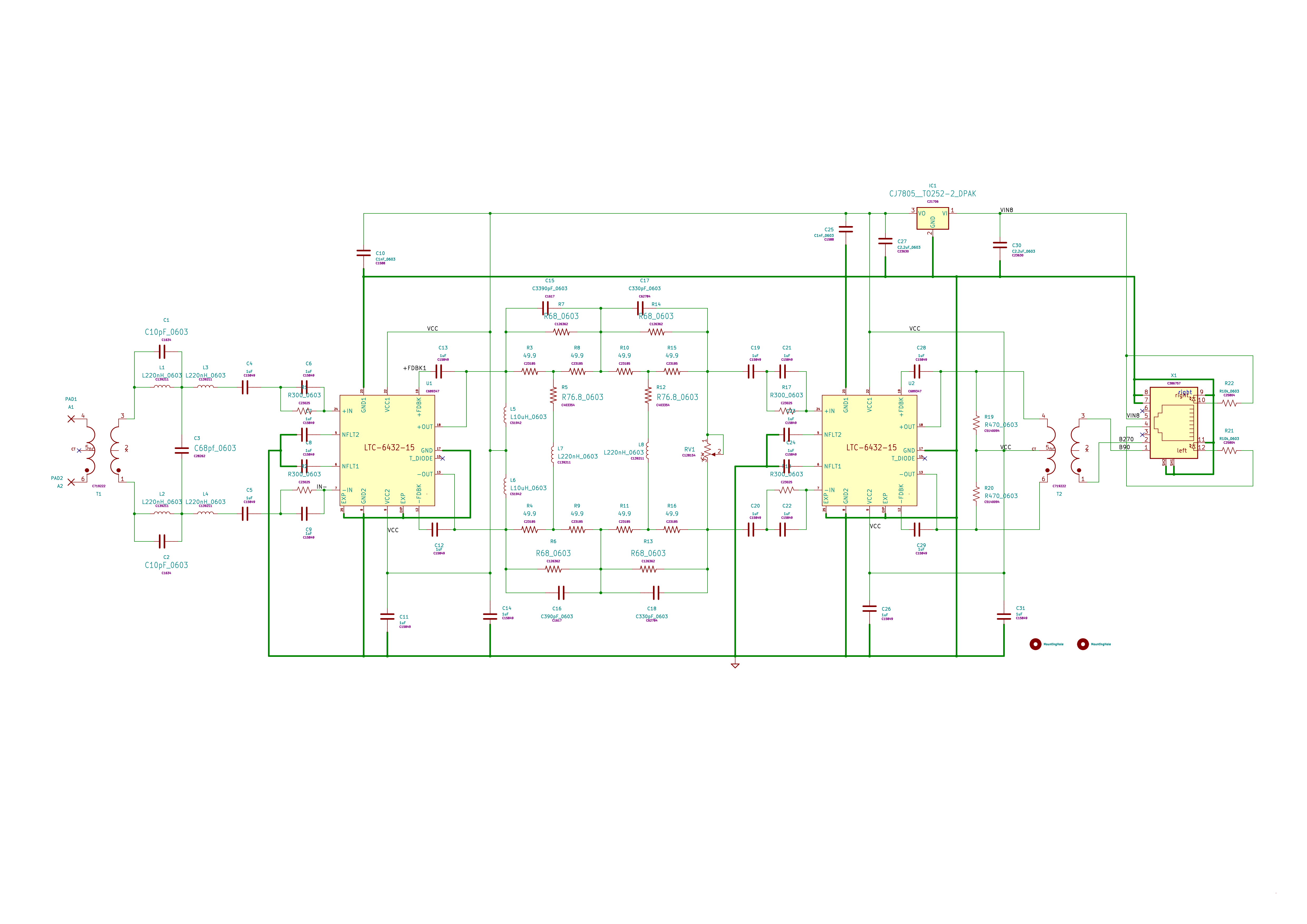
The schematic follows but for
better viewing of the design, download the Kit
file from the Material List
below , unzip it and drop the .sch or .pcb file onto kicanvas
from
a web browser.

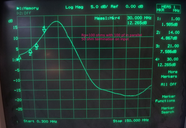
Gain is adjustable, but the shape is shown here:
Upon receipt of the assembled Shack and Preamp PCBs from the
manufacturer, simple preliminary testing should be
performed. This should include the absence of shorts on the power
supply input and the output of the 7805 LDO. The board will already have
been flying probe tested at manufacture and physically examined after
all components were soldered but one more test after delivery is good
insurance.
Once there is confidence that everything is OK with the Shack and
PreampB PCBs, 12VDC power can be applied to the Shack PCB and 8V output
voltage measured and the adjustment set for 8V. If possible
it is a good idea to provide the 12VDC from a current limited bench
power supply as extra insurance. Normally PreampB current should
be no more than .5A and PreampB so setting a current limit point
slightly higher than this will ensure that if something has gone wrong,
excessive current can't flow and damage a component.
As given on the material list, the preamps are easily mounted in
common PVC 3/4" electrical T boxes. These accept 3/4" PVC pipe readily
found in hardware stores and used for both electrical and landscape
water systems. Two holes need to be drilled to mount the Preamps.
Place some thermal padding between the bottom of the PCB and the box to
help remove heat from the PCB. PreampB dissipates more than 4 watts so
keeping the PCB relatively cool in hot climates is important. This
technique has worked well even in climates that got quite hot in summer
and cold in winter.
The PVC hardware may not be readily available outside of North
America. For that situation, the user will need to find a way to
accomplish the same goals; an enclosure that can keep the PCB dry, keep
it adequately cool while providing connection for the antenna rods or
wires. Ham ingenuity and a knowledge of suitable locally available
enclosures may be necessary for this. Identifying all possibilites world
wide is well beyond the scope of these instructions.


