Single Antenna System (SAS)
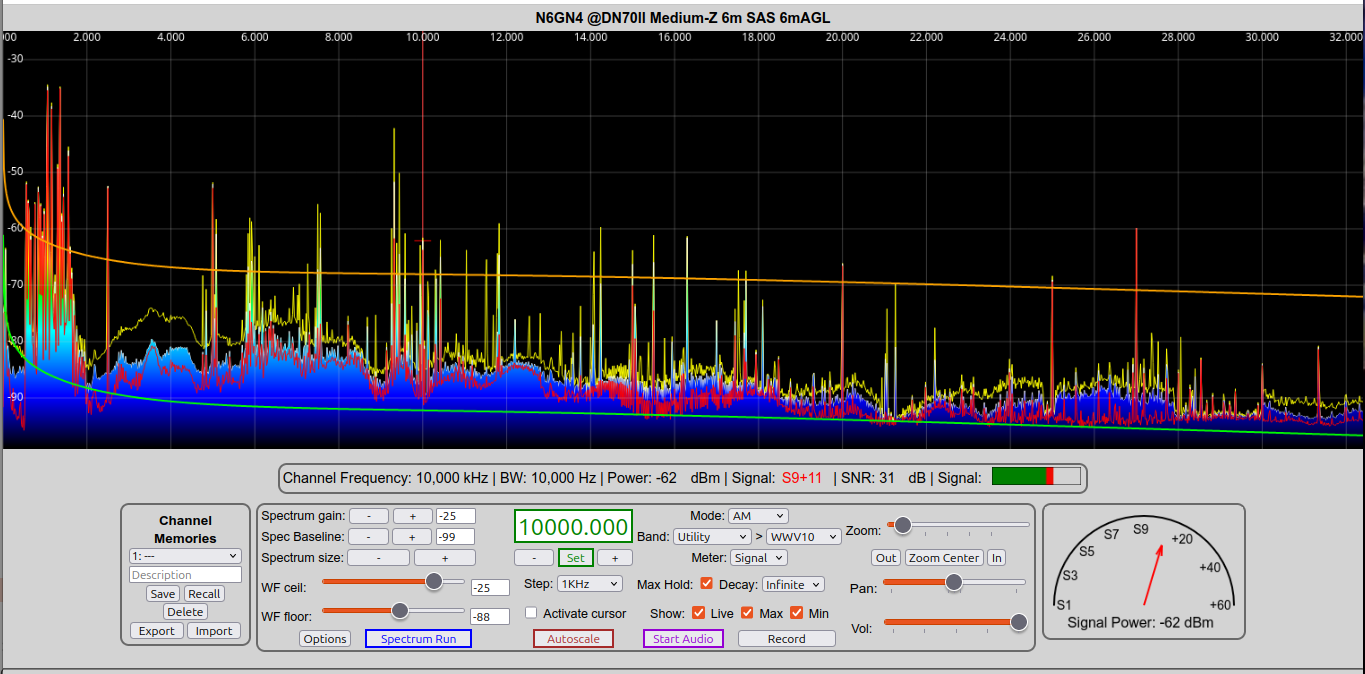
This is a Single Antenna 10kHz-30 MHz receiving system, which can be generally useful from 1kHz to 200 MHz. It is a larger version of the Field Probe and the original PreampA/2m-dipole projects. PreampA and SAS are low noise antenna system capable of approaching or achieving the ITU "Quiet Rural" regional noise limit over the entire LF-HF range when and where a suitable situation exists. Like the other n6gn OSHW broadband receive system designs it is a highly symmetrical/differential probe. Because it uses a symmetric antenna rather than a monopole referenced to earth or to a radial system, as are many commercially available broad band antenna systems, it can provide much higher rejection of common mode feedline and ground noise that can easily reduce system performance. Also because it is a probe rather than a resonant/matched structure it can be an extremely broad band system that can provide effective coverage from audio frequencies well into VHF.
A goal of this system is to approach performance dictated by regional noise limitations as described by Rec. ITU-R P.372-16 rather than by unwanted local noise sources present at a particular location.
Caution: The broadband antenna system described here and on associated pages MAY NOT WORK FOR YOU ! It cannot operate well in every possible environment. Even with modifications and adjustments being identified and described and with very considerable extra effort there will be situations too difficult to manage. An entirely different receive system approach may be required.
This kit is not a simple solution by itself. Simply obtaining or building all the kit pieces necessary to install the hardware is required but not sufficient. Proper deployment of a complete system is at least, if not more, important than the equipment itself. Not understanding and following this advice may result in wasted time, energy and money !!! Background for this kind of wide-band receiving systems is provided in a Broadband Receive Systems overview. PLEASE read that background and also Deploying a Single Antenna System before beginning the building process..
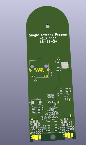
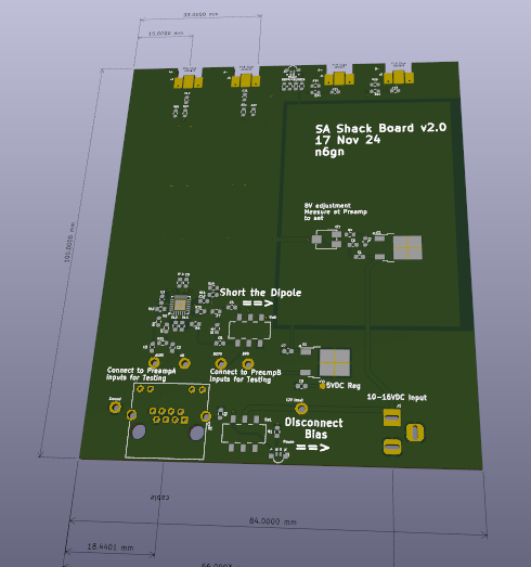
A newer version of the original very broadband design is now provided in the Material List. This allows optioning for either high Impedance (HiZ) or medium impedance (MedZ) preamplifier inputs. Both options are followed by CAT5 feedline and the ShackBoard version 2.
Please Note: For many if not most uses, the MedZ option will be the best choice. While the HiZ version can operate with smaller dipoles and to lower frequency, it has a much higher noise floor limit and poorer distortion performance compared to the MedZ option. Unless Audio-MF operation is a high priority, The MedZ option is recommended.
How this Receive-Only Antenna System is DIFFERENT from Traditional Antennas
In order for the Single Antenna system (SAS) to become a useful and valuable solution capable of achieving excellent results at a particular location it is important to recognize some ways it is different from a traditional antenna.
- Fundamentally the HiZ SAS operates as a probe NOT as a conventional matched antenna.
- The MedZ option operates more as a matched antenna in some ways.
A matched dipole antenna has "joined monopoles" where current passes through the center to the other element. It is operated as a resonator, storing energy with reflected energy from each tip re(reflecting) from the other. A probe antenna is one with unterminated monopoles where no current is coupled from one monopole to the other or into a termination. It is not a mechanism that transfers power from or to an incident wave in space. For this reason it is only used for receiving.
The SWTL understanding of a dipole offers an idea of what is occurring in this case of two colinear elements operated as a probe. For this usage, the monopole elements are still considered as 377 ohm SWTLs connected to a radiation resistance and "probing" a region of space but because there is no current delivered to a load or shared between the two monopoles the structure does not operate in the same manner nor have exactly the same pattern as a matched dipole.
When viewed using the SWTL model of a dipole, from within a 73 ohm environment a traditional matched halfwave dipole can be viewed as a resonator having a Q of ~10 . Two 377 ohm transmission lines, the monopole elements, are terminated in a radiation resistance of approximately ten time this value. While perfectly matched at the frequency of the "first resonance", considered as a broadband device it has a Q which prohibits its use as a well-matched multi-decade bandwidth antenna. See the Fano-Bode limit. In comparison, two monopoles separated and acting as an unterminated probe have a Q of zero, if the concept of Q even applies when no energy transfer is involved. No significant current ever flows from these elements into the circuits that follow. No significant power storage or transfer is involved. Active circuits which follow provide energy to produce output power rather than the incident wave being detected.
For a probe antenna such as this, the differential voltage at the center is the same as the differential voltage between the tips. As the electrical length of the structure increases, the two apertures at the tips that are associated with coupling to a wave in space separate. Voltages presented at the preamp input first increase from the short dipole case where there is almost complete aperture overlap to a maximum at large electrical length where there is complete separation. As these individual apertures become non-overlapping, the voltage alternates between a maximum and zero as the phase of the voltage generated from a boresight intercepted wave at each tip changes. Thus, although the pattern varies wildly as the length is increased and apertures move apart, the total effective aperture increases only to twice its initial value. The main lobe alternates from a maximum at boresight for odd half-wavelengths to minima near even multiples of a wavelength. At these even multiples the main lobe splits and has one or more maxima. See A New Antenna Model.
The differences between the HiZ and MedZ options need to be kept in mind since they make not only the useful bandwidth and noise characteristics but also the strong signal performance and to degree the elevation patterns of these two options different.
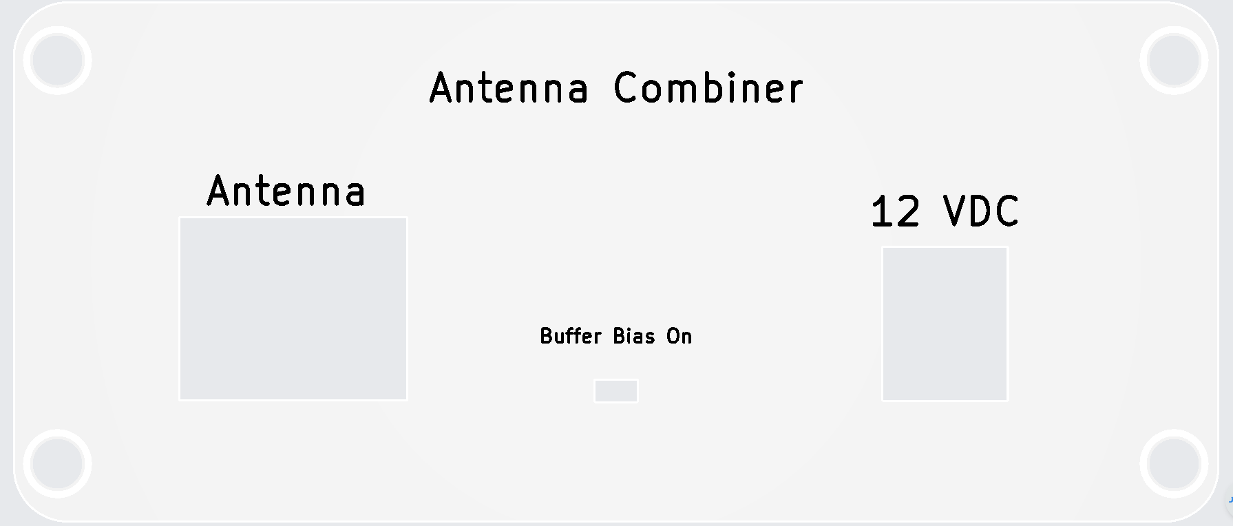
A simplified block diagram of an entire broadband SA & SDR system follows. This includes not only the physical antenna conductors but simplifications of the active electronics involved. This block diagram shows the two options:
- HiZ option wherein the monopoles connect to extremely high impedance, unity gain amplifiers and the system acts as a probe
- MedZ option where the monopoles connect at a different point to a several hundred ohm input impedance that can provide lower noise and better performance in a strong signal environment.

Two Options: High or Medium Impedance
High Impedance Option: Broadest Bandwidth
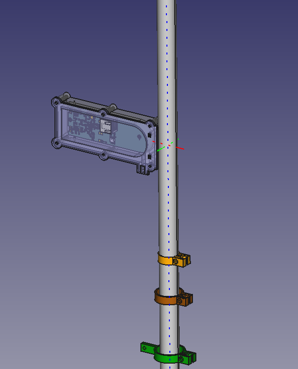
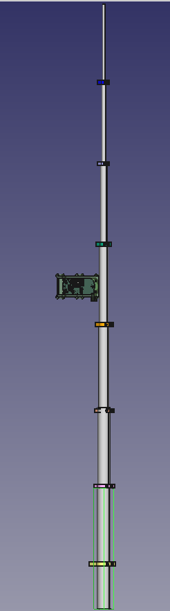
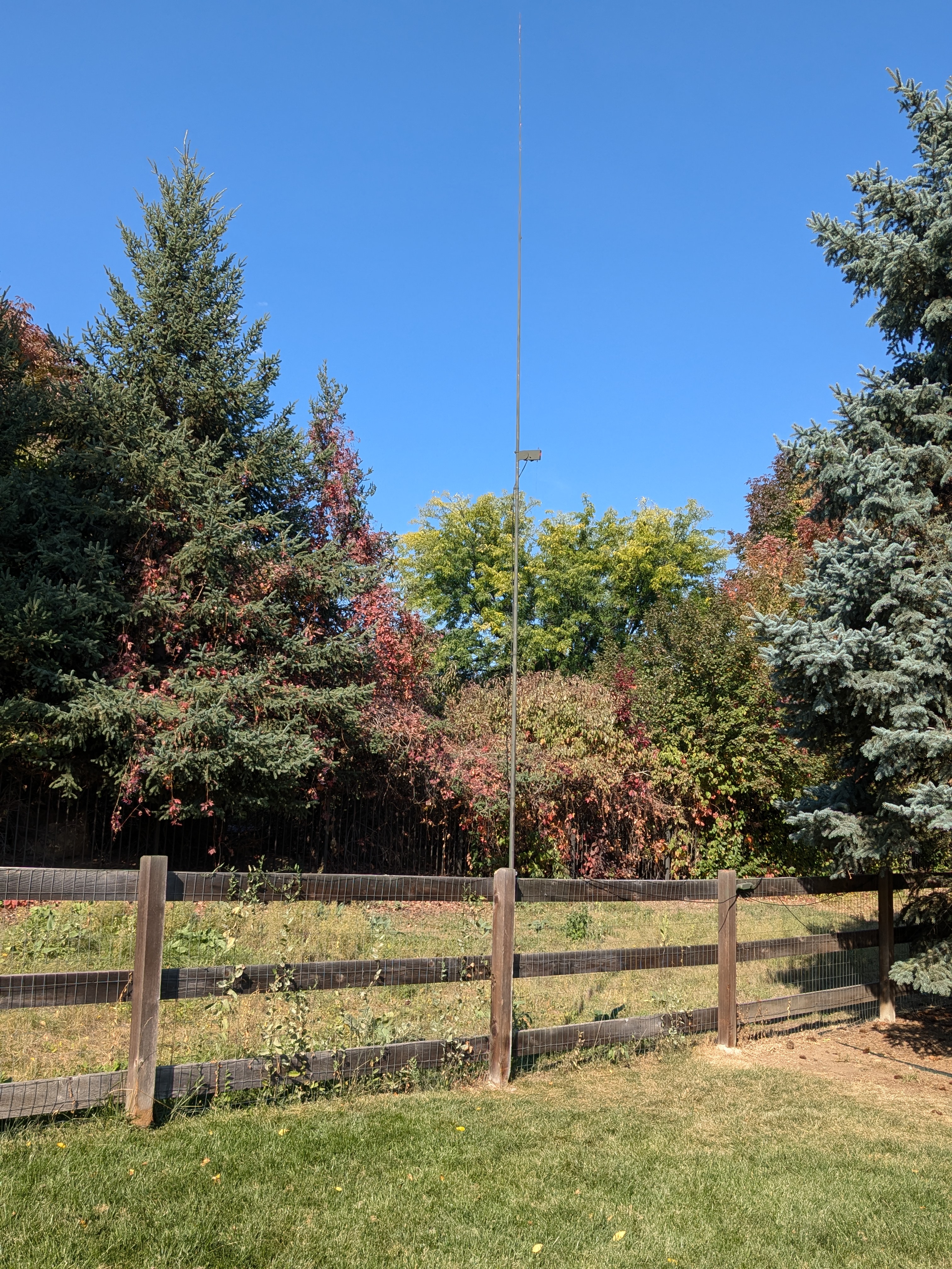
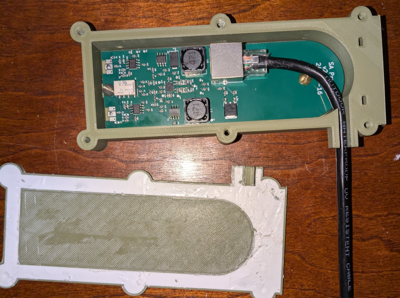
In the HiZ option a high CMRR preamplifier is mounted inside a 3D printed plastic housing located near the middle of an insulating fiberglass mast and fed with standard CAT5 cable as shown below. Operation from Audio Frequencies through VHF is achieved due to the very high impedance OpAmp unity gain input stages. Even though the attached dipole is electrically extremely short at the lowest frequency limit of the system, the high impedance allows relatively efficient transfer of the very small signal voltage at the buffer amplifier inputs while offering suitably low noise floor and acceptable distortion characteristics which permits approaching the targeted ITU regional limits It will not be able to reach the regional noise limit at upper HF in the quietest locations but may be completely adequate in typical City, Suburban and even many Rural locations.
This system employs the SWTL model of a dipole and through the use of small .5mm diameter conductor elements (not shown) can allow a CAT5 feedline (also not shown) to run parallel along the mast for most of the monopole conductor's length before finally exiting near the base. This can be done without upsetting antenna balance and symmetry which might otherwise unbalance the structure and possibly raise common mode noise ingress and decrease capability. Additional measures are taken to route the feedline to avoid shadowing of the monopole's aperture which is located in the region of space near its tip.
MedZ Option: Lower distortion & Traveling Wave antenna use
As noted above, the MedZ option of the SAS does not have the same bandwidth nor exactly the same pattern as the HiZ one. Current is delivered to the SAS Preamp such that both mismatch loss and aperture and pattern are different. The MedZ option can not provide the same very low frequency limit but it can still operate from MF through VHF while at the same time eliminating the noisier high impedance OpAmp buffer. Use of only the quieter ADA4930 provides as much as 10 dB improvement in strong signal protection and lower noise. Input signals as large as 2 V p-p may be tolerated without generation of significant unwanted inter-modulation distortion (IMD). So when used even with larger dipoles it does not have coverage down to VLF but it is able to tolerate antennas and environments producing three times the signal voltage. Optimum dipole size will be determined by pattern, noise floor requirements, the strong signal environment and practical constraints for a particular application.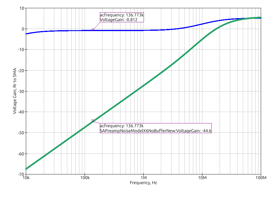
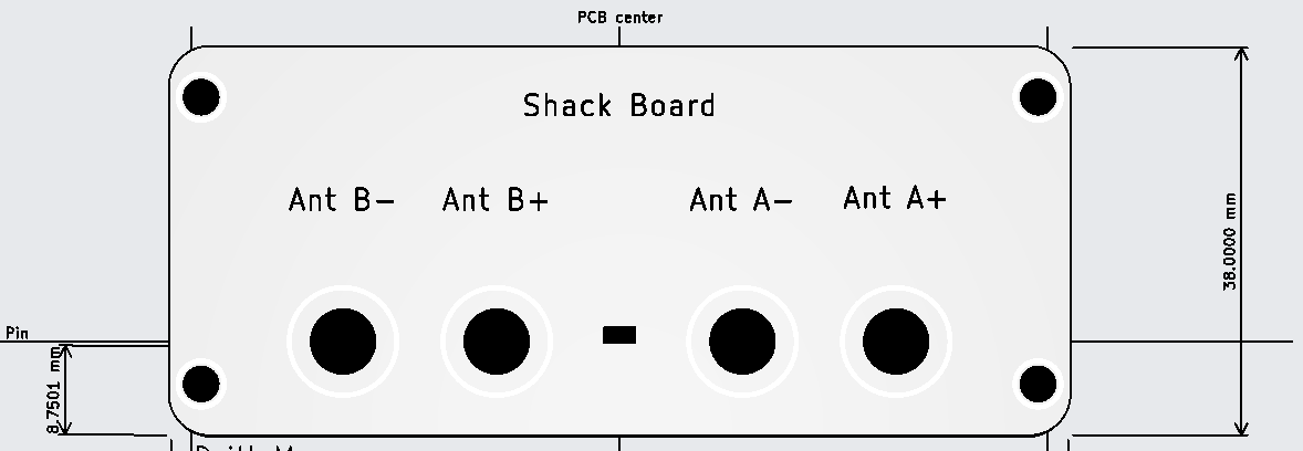
Two Function Levels: Utility or Performance - selected by configuration at the ShackBoard
Utility Level
The Shack Board has two independent, isolated 50 ohm outputs, each of which covers the audio through VHF frequency range. These outputs include ADA4930 common mode signals and have a noise level of around -140 dBm/Hz. For situations where the incoming noise floor from the antenna/preamplifier is a few dB higher than this, there will be no significant degradation of SNR and the dual wideband outputs may be adequate and convenient to supply two receivers. The very low frequency limit of these outputs allows reception of VLF and even AF signals. NO combining of the two outputs is necessary.
Nominal gain from the antenna connections of the Preamp to one of the A outputs is -3 dB,
Performance Level
In Performance level operation, an anti-phase combiner is added to combine the two Shack Board A outputs in a manner which cancels the CM noise and produces a single output having a much lower noise floor, near -160 dBm/Hz, a 14 dB noise figure. This is combination is provided by an external broadband transformer used in a 3dB splitter/combiner configuration. But because of the transformer bandwidth limitations, the low frequency limit of the system will generally be above 10 kHz, possibly higher depending upon the SDR which follows. This configuration is important in situations which have the lowest incoming/regional noise floor from the antenna/preamp but do not require VLF or lower frequency operation.
Either of these two levels may be selected simply by adding or omitting the anti-phase combiner and two connecting cables.Modeling Performance
see Antenna Factor
Mounting and Interconnection
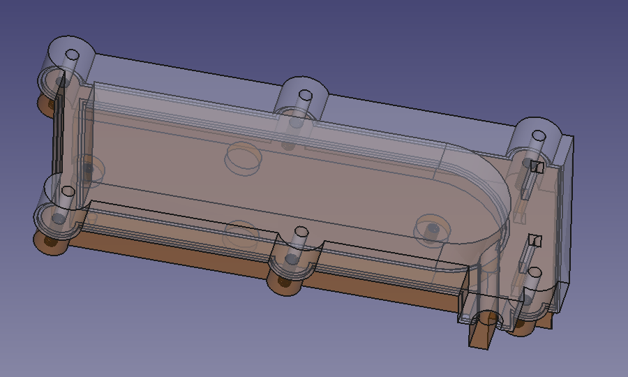
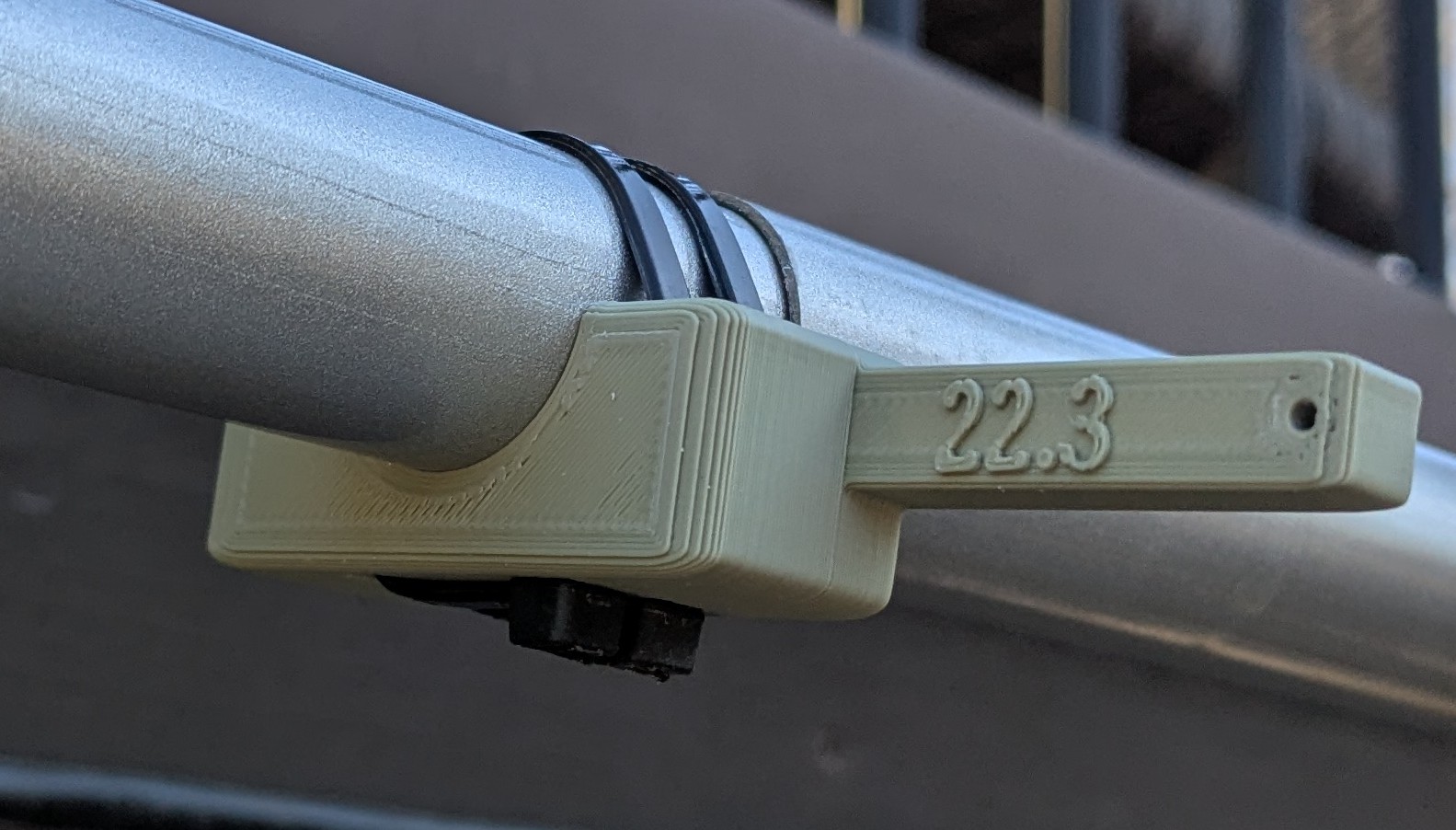
3D printed plastic clips are used along the mast to hold the conductor in proper position. Clamping this way also adds extra assurance that the mast sections won't loosen and collapse.
- Highly symmetric differential inputs and outputs
- CMRR as great as - 50 dB to 30 MHz (but also a function of antenna balance/symmetry).
- Connects to Shack Board for power, RF termination and CMRR verification
- optional high and medium impedance, high-Z and medium-Z, applications
- both options intended for use with 7m-10m fiberglass masts, ground mount and 3D printed mounting HW shown in the Material List
- High-Z Input referenced noise is 2 - 3 nV/rt(Hz), input buffer limited
- shaped gain to optimize noise floor with overload damage protection
- noise floor near -160dBm/Hz.
- Medium-Z (~755 ohms differential) input referenced noise as low as 1.2 nV/rt(Hz), CAT5 driver limited
- Use with 30m (nominal) length standard CAT5 cable, in many environments greater length possiblewithout degradation
- SAPreamp is used with associated Shack Board, 12VDC @ ~100mA
The ADA4930-1/ADA4930-2 differ from conventional op amps in that they have two outputs whose voltages move in opposite directions and an additional input, VOCM. Like an op amp, they rely on high open-loop gain and negative feedback to force these outputs to the desired voltages. The ADA4930-1/ADA4930-2 behave much like standard voltage feedback op amps and facilitate single-ended-to-differential conversions, common-mode level shifting, and amplifications of differential signals. Like op amps, the ADA4930-1/ADA4930-2 have high input impedance and low output impedance.
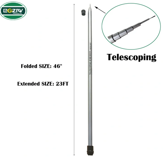 Telescoping
Fiberglass Mast
Telescoping
Fiberglass Mast